Optical reader having two-dimensional solid state image sensor and light generator

a technology of image sensor and light generator, which is applied in the direction of visual presentation using printers, instruments, electromagnetic radiation sensing, etc., can solve the problems of affecting the reading process. the decoding operation lags behind the scanning operation, so as to solve the problem of ignoring the decoding operation for a long tim

Inactive Publication Date: 2004-12-30
HAND HELD PRODS
View PDF99 Cites 34 Cited by
  • Summary
  • Abstract
  • Description
  • Claims
  • Application Information

AI Technical Summary

Benefits of technology

[0067] More particularly, processor 42 is preferably a general purpose, off-the-shelf VLSI integrated circuit microprocessor which has overall control of the circuitry of FIG. 1, but which devotes most of its time to decoding image data stored in RAM 45 in accordance with program data stored in EROM 46. Processor 44, on the other hand, is preferably a special purpose VLSI integrated circuit, such as a programmable logic or gate array, which is programmed to devote its time to functions other than decoding image data, and thereby relieve processor 42 from the burden of performing these functions.
[0335] With "bullseye" type symbologies, the presence of the central finder is indicated by the emergence of easily recognized numerical patterns that are derived from the above-mentioned succession of bit representations using a new finder identifying algorithm to be described hereinafter. With the "peripheral" and "waistband" type finders, the finders may be identified by means of the known finder identifying algorithms for the DataMatrix and Code One symbologies. If symbols with more than one type of finder are being autodiscriminated, these finder identifying algorithms may be applied alternatively and successively, i.e., as candidate algorithms, until one actually succeeds, and makes decoding possible.

Problems solved by technology

Readers of the above-described type have the disadvantage that, if they are operated under relatively heavy decoding loads, i.e., are required to rapidly scan symbols that have a relatively high data content, the tracking relationship or synchronism between the scanning and decoding phases of the reading process will break down.
This is because under heavy decoding loads the decoding phase of a read operation takes longer than the scanning phase thereof, causing the decoding operation to lag behind the scanning operation.
While this time lag can be dealt with for brief periods by storing the results of successive scans in a scan memory and decoding the results of those scans in the order of their occurrence when the decoder becomes available, it cannot be dealt with in this way for long.
This is because, however large the scan memory, it will eventually overflow and result in a loss of scan data.
This is in spite of the fact that the 1D / 2D autodiscrimination is known to involve heavy decoding loads of the type that give rise to tracking problems.
As new and / or improved 1D and 2D bar code symbologies, and as additional 1D and 2D decoding programs come into widespread use, previously built optical readers may or may not be able to operate therewith.
To the extent that they cannot operate therewith, such previously built optical readers will become increasingly obsolete and unusable.
Because of the expense of the former and the time delays of the latter, neither of these approaches may be practical or economical.
The above-described problem is compounded by the fact that, if an optical reader is not equipped to operate as a tracking reader, it may not be possible to reprogram it to use an autodiscrimination program that is designed to be executed in conjunction with tracking.
Alternatively, the scan rate may be decreased, although this reduction will adversely affect performance when low data content symbols are read.
This skipping also reduces the chances of a misread.
There is no reason in principle, however, why tracking options C4-C6 cannot be made user selectable as, for example, by the inclusion of suitable menu symbols in the User's Manual.
The copying of the flash routine to RAM is necessary because the EROM cannot be written to when the apparatus is reading or operating from the EROM.
If, however, any line of data has not been successfully stored, block 1075 will direct the processor to a block 1080 which causes it to output an error message and exit the program.
Under heavy decoding loads, however, prior art methods do not allow sufficient time for decoding.
When this occurs new scan data will overwrite old scan data which was not processed, thereby causing a loss of large blocks of scan data.
As a result, there cannot arise a situation, such as that which can arise with the prior art, in which there is a massive loss of scan data.
If the decoding load becomes extremely heavy, however, it is possible that more old blocks of scan data are skipped over than is advisable.
Secondly, a software interrupt routine is triggered by the scanning hardware which maintains the loose linkage between the hardware and the software of the present embodiment.
Secondly, software interrupt routines are triggered by the scanning hardware to maintain the loose linkage between the hardware and the software of the present embodiment.
However, under a heavy information load it can be seen that the prior art methods 3140 did not allow sufficient time for decoding.

Method used


Image

  • Optical reader having two-dimensional solid state image sensor and light generator
  • Optical reader having two-dimensional solid state image sensor and light generator
  • Optical reader having two-dimensional solid state image sensor and light generator

Examples


Embodiment Construction

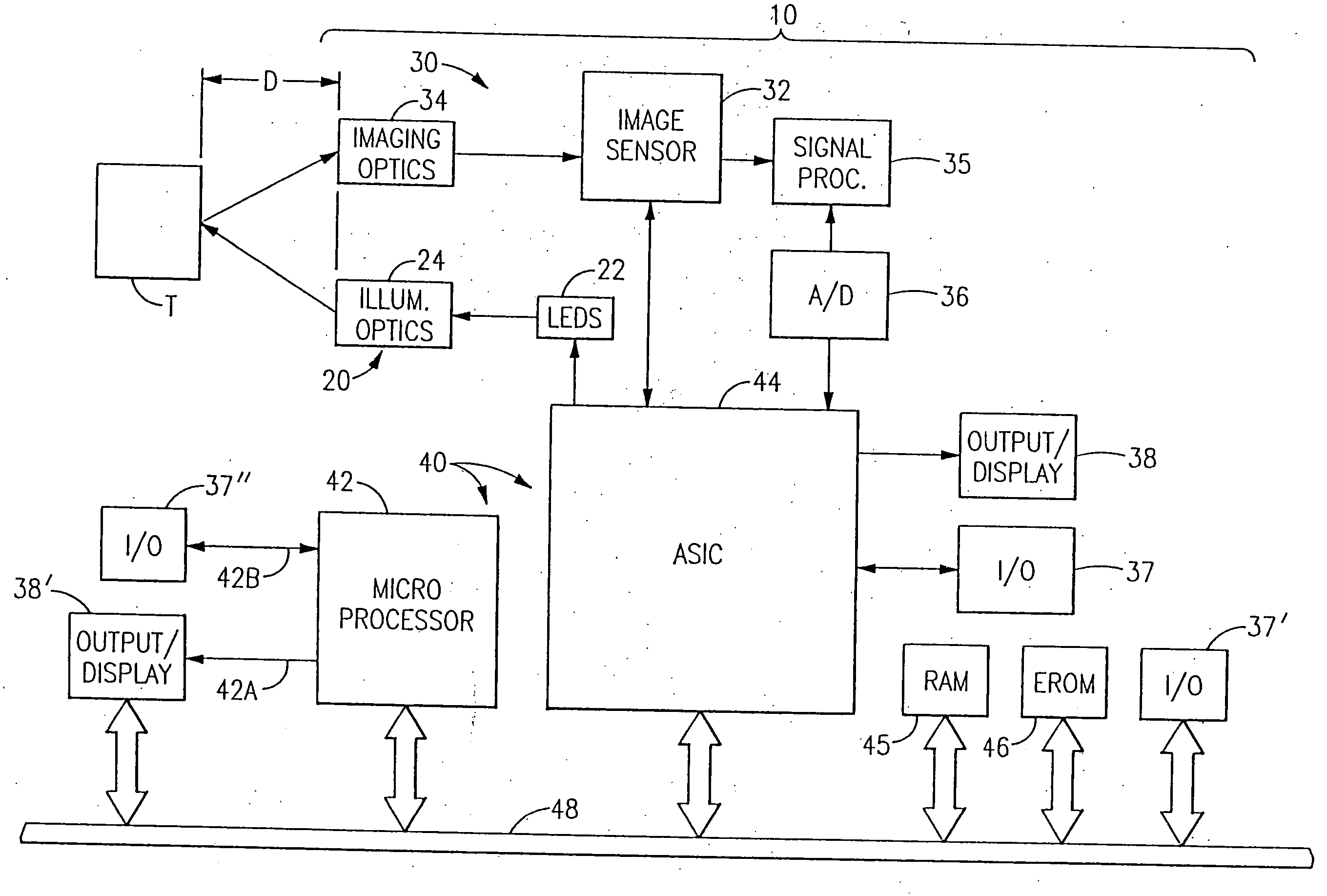
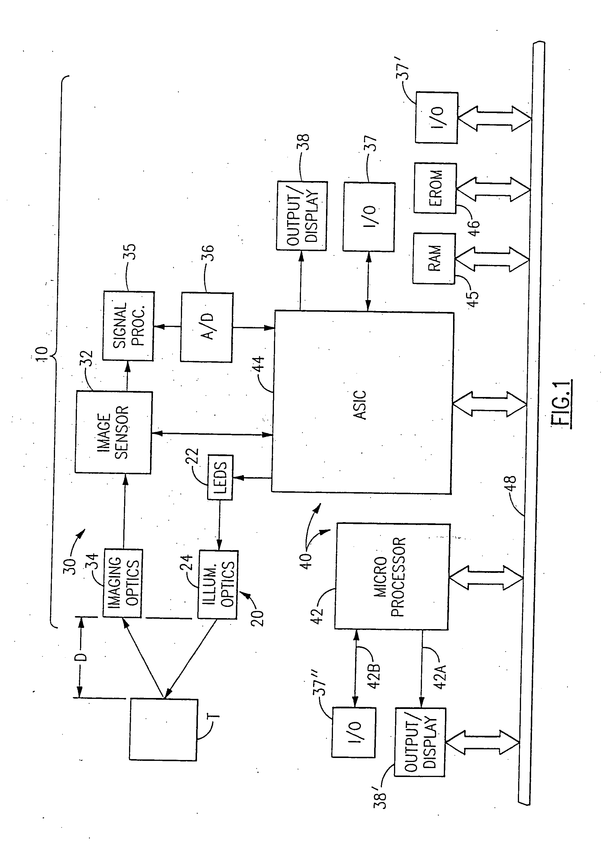
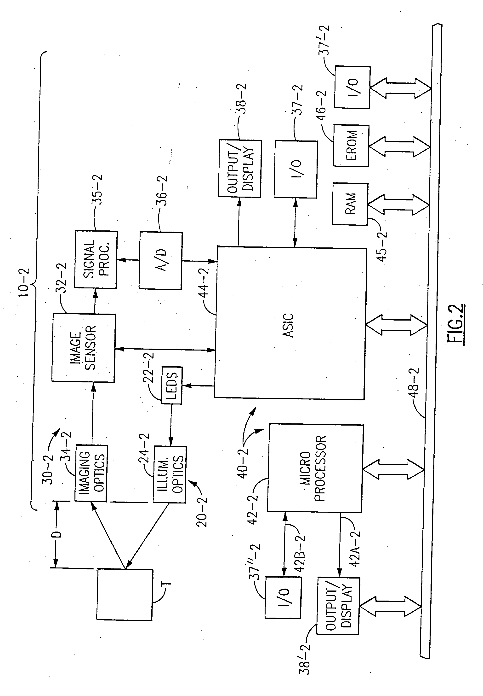
[0350] Referring to FIG. 34 there is shown a block diagram of a bar code reader of a type which is suitable for use in practicing the present invention. This bar code reader may be a D bar code reader of the type sold by Welch Allyn, Inc., Skaneateles, N.Y. under the model designation ST-3000-22, provided that certain modifications to be discussed later are made thereto.

[0351] The bar code reader includes an illumination system which may comprise a plurality of 660 nm light emitting diodes 16 that illuminate a narrow strip or slice of a bar code symbol 4018. Reader 4010 also includes focusing optics 4019 which may be of the type described in U.S. Pat. No. 5,291,008, which is assigned to the assignee of the present invention, and incorporated herein by reference. Focusing optics 4019 causes light returning from the bar code symbol along a receive path 4014 to be focused or imaged upon a 1D image sensor 4017 which may be of the charge coupled type. Sensor 4017 develops analog signals ...


PUM


Abstract

A bar code reading device processing electronic representations in the decoding of bar code symbols, which includes an illumination assembly and a solid state image sensor. The bar code reading device may have improved reprogramming features and improved menuing features.

Description

[0001] This application is a continuation of copending U.S. patent application Ser. No. 10 / 227,889 filed Aug. 26, 2002, which is a continuation of U.S. patent application Ser. No. 09 / 651,162 filed Aug. 30, 2000, which issued as U.S. Pat. No. 6,491,223, which is a continuation of U.S. patent application Ser. No. 09 / 385,597 filed on Aug. 30, 1999, which is a continuation-in-part of U.S. patent application Ser. No. 08 / 839,020 filed Apr. 23, 1997, which issued as U.S. Pat. No. 5,965,863 on Oct. 12, 1999, which is a continuation-in-part of U.S. patent application Ser. No. 08 / 697,913 filed on Sep. 3, 1996, which issued as U.S. Pat. No. 5,900,613 on May 4, 1999, which is a continuation-in-part of U.S. patent application Ser. No. 08 / 516,185 filed Aug. 18, 1995, which is now abandoned, which is a continuation-in-part of U.S. patent application Ser. No. 08 / 205,539 filed on Mar. 4, 1994, which issued as U.S. Pat. No. 5,463,214, the aforementioned Ser. No. 08 / 697,913 filed Sep. 3, 1996 also bei...

Claims


Application Information

Patent Timeline
Patent Type & Authority Applications(United States)
IPC IPC(8): G06K7/10G06K7/14G06K17/00G06K19/06
CPCG06K7/10544G06K7/10851G06K7/14G06K7/1491G06K17/0022G06K19/06037G06K2207/1017G06K7/10821
Inventor LONGACRE, ANDREW JR.HUSSEY, ROBERT M.PIDHIMY, JOHN M.
Owner HAND HELD PRODS
Why Eureka
Try Eureka