
Method of making pile fabric

a pile fabric and pile technology, applied in the directions of knitting, knotting, transportation and packaging, etc., can solve the problems of visual “break” in the surface coverage provided, undesirable surface coverage breakage, and uneven pile formation

Inactive Publication Date: 2005-01-06
SAGE AUTOMOTIVE INTERIORS INC
View PDF16 Cites 2 Cited by
  • Summary
  • Abstract
  • Description
  • Claims
  • Application Information

AI Technical Summary

Problems solved by technology

Such bending typically causes the pile-forming yarns to spread apart, undesirably exposing a portion of the underlying base fabric.
That is, bending of the fabric causes a visual “break” in the surface coverage provided by the pile yarns.
Such a break in surface coverage is undesirable.
However, such high pile densities may not be completely effective in avoiding pile separation.
Furthermore, high pile density fabrics are expensive and relatively heavy, which is undesirable.
While such textured yarns may provide beneficial surface coverage characteristics, they may pose problems in fabric manufacture while also adding complexity and expense due to the texturizing processes required.
In addition, the use of textured yarns may give rise to an enhanced potential for the occurrence of single end defects and non-uniformity in dyeing, which are undesirable.

Method used

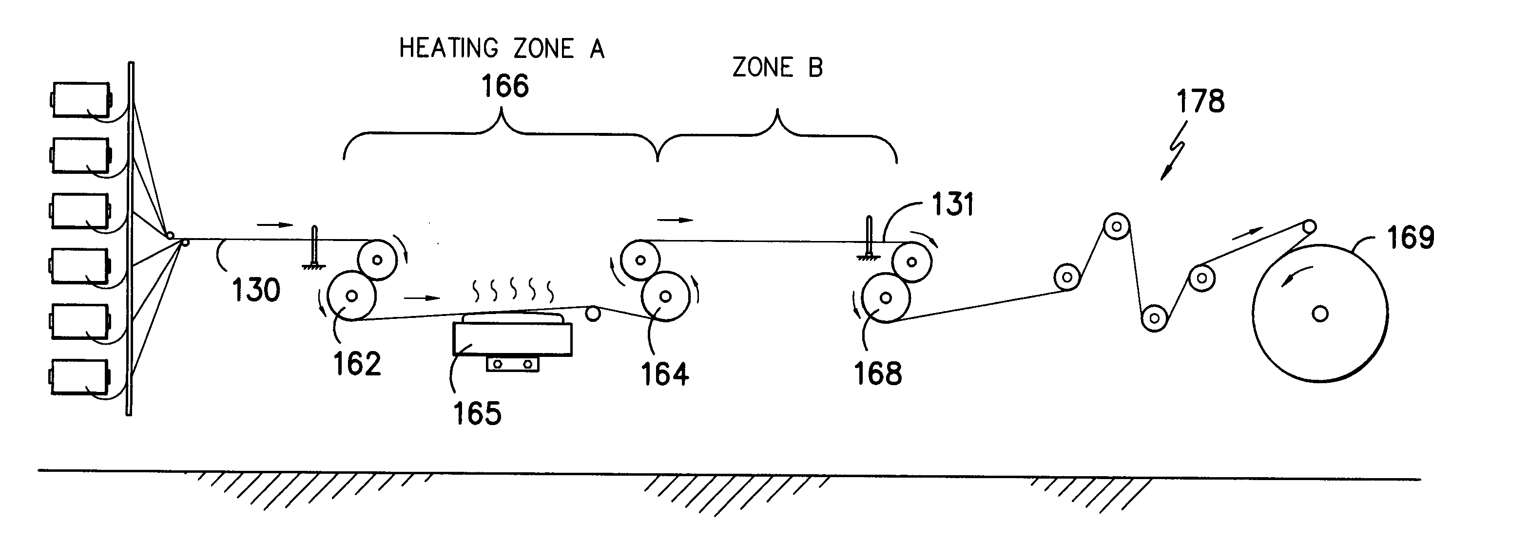
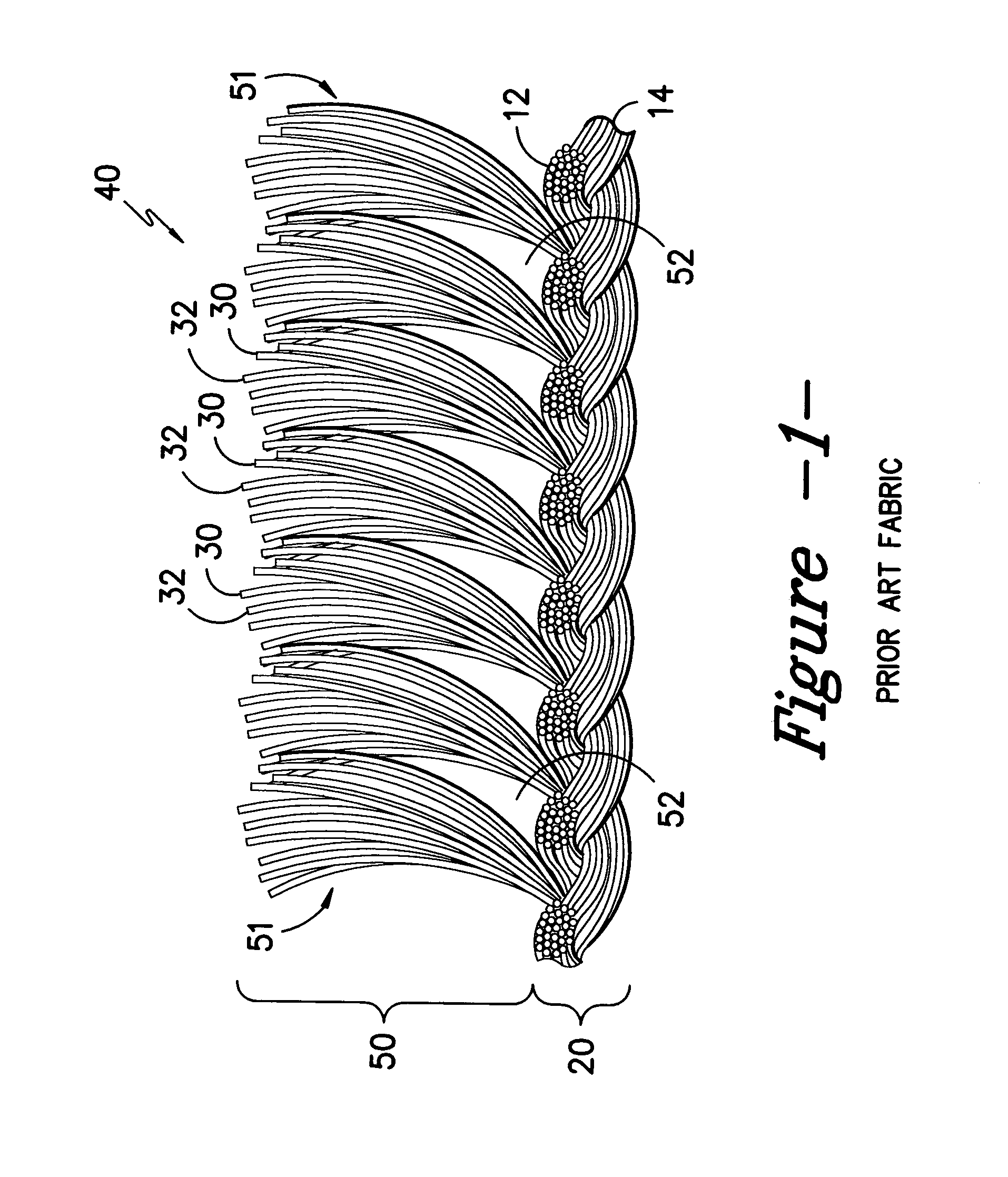
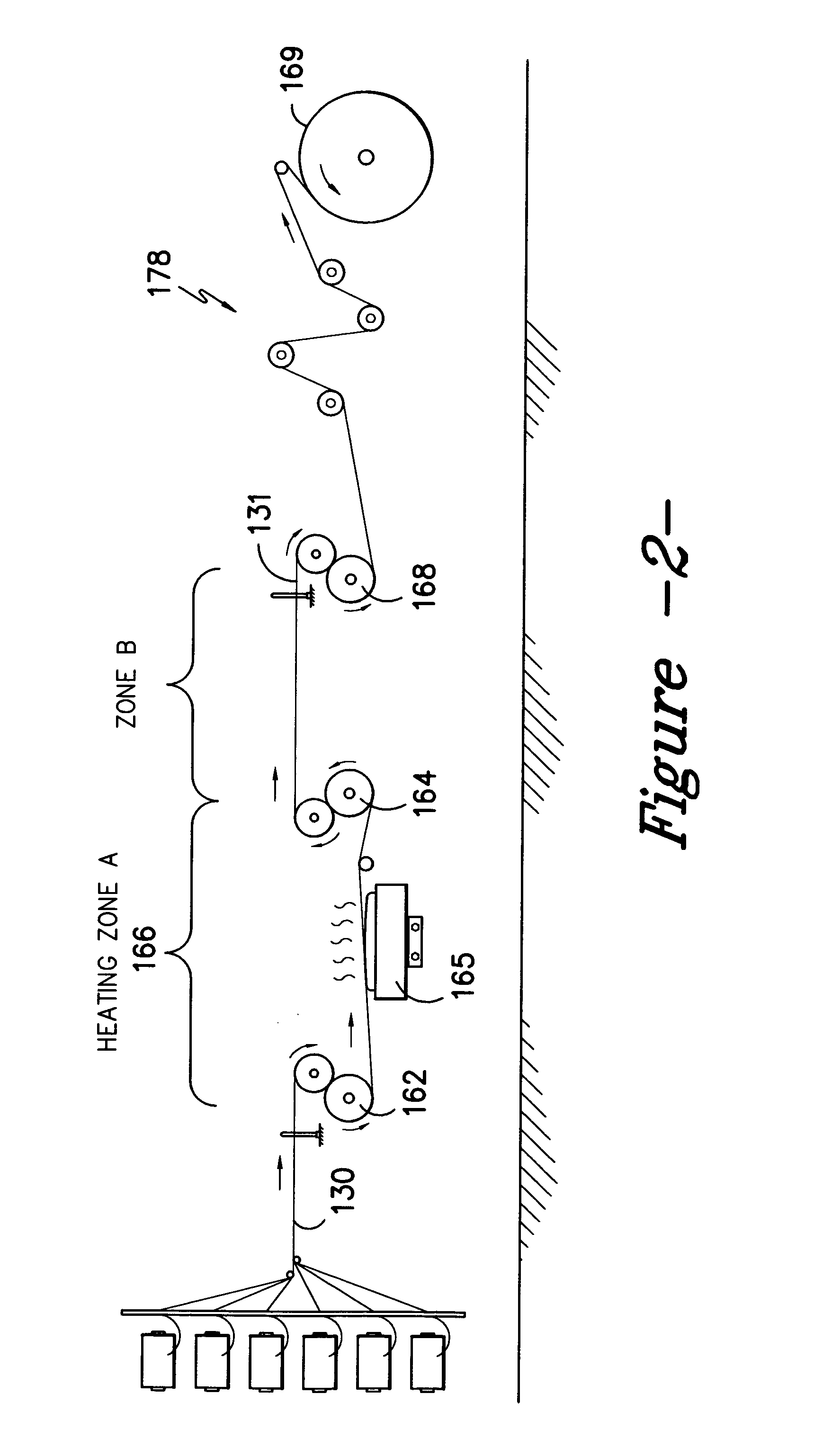

Image

  • Method of making pile fabric
  • Method of making pile fabric
  • Method of making pile fabric

Examples


examples

The initial fiber samples of the invention in Samples A and B of Table 2 below were run using round polyester partially oriented yarn (POY), designated M-3M001, which was obtained from Nanya Plastics Company of South Carolina USA, according to the following conditions.

Formation and processing parameters for the fabrics of Samples A and B are set forth in Table 1 below. The knitting of each was accomplished upon a 32 Gauge Double Needle Bar Warp Knitting machine. The fabric was formed in a “sandwich” structure at a six bar construction with ground yarns (forming the fabric base) carried in bars 1, 2, 5 and 6 and pile yarns carried in bars 3 and 4. The pile-forming yarns were characterized by the meta stable state, due to the heat shock effects provided in the practice of the invention.

TABLE 1Formation and Processing ParametersBack Bar YarnBars 1 and 6(260) 212 / 36 semi-dull round polyesterRunner Length = 120.0″Mid Bar YarnBars 2 and 5(260) 150 / 36 semi-dull round polyesterRunner L...


PUM


Abstract

A pile fabric may be employed in automotive, furniture upholstery and other applications. Pile surfaces on such fabrics may be provided in tufts, or collections of fiber bundles, arranged in rows upon a base portion. Fabrics and methods of making fabrics which minimize the average amount of void space between respective tufts or rows are disclosed. Fabrics which provide more effective overall fabric coverage upon base portions of the fabric are described. A method of “heat shocking” fibers during the drawing of said fibers to pre-stress the fiber and thereby produce a fabric having greater bloom or bulk is disclosed. Providing differential heat history to predetermined portions of the fiber may be a suitable manner of obtaining a fiber which can be used to form a fabric having greater bulk.

Description

BACKGROUND OF THE INVENTION Pile fabrics such as velours, velvets, and the like may be formed using a “sandwich” method in which two fabrics substrates are woven or knitted in face to face relation with the pile ends interlocking. A cutting blade slits through the center of the “sandwich”, cutting the pile ends to produce two separate pieces of fabric. Each cut piece provides a multiplicity of yarns project outwardly away from the base so as to define a user contact surface. A common application for pile fabrics is in the covering of seating structures and other interior components for use within transportation vehicles. Such fabric is also used in the manufacture of furniture. In forming a pile fabric around portions of a seating structure, the fabric bends around sharply defined radius portions of the surface being covered. Such bending typically causes the pile-forming yarns to spread apart, undesirably exposing a portion of the underlying base fabric. That is, bending of the ...

Claims


Application Information

Patent Timeline
Patent Type & Authority Applications(United States)
IPC IPC(8): D04B21/02
CPCD10B2503/04D04B21/02
Inventor WILLIAMSON, CURTIS BRIANKELLER, MICHAEL
Owner SAGE AUTOMOTIVE INTERIORS INC
Learn More