
Multi-hulled vessel

a multi-hulled, nautical technology, applied in the direction of waterborne vessels, floating buildings, vessel construction, etc., can solve the problems of comparatively small craft, comparatively heavy or comparatively complex rigid connecting structures, and no attempt to provide a totally rigid connection structure, etc., to avoid pollution

Inactive Publication Date: 2005-01-06
VAN DIJK JAC W
View PDF6 Cites 1 Cited by
  • Summary
  • Abstract
  • Description
  • Claims
  • Application Information

AI Technical Summary

Benefits of technology

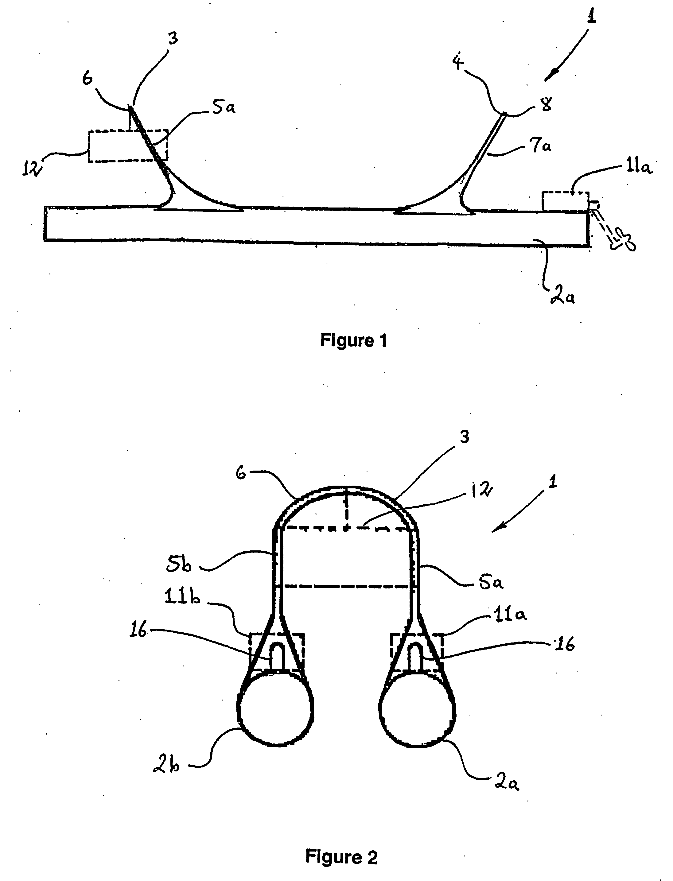
[0021] Each connecting structure may lie substantially in a plane. Such an arrangement is convenient and comparatively simple to build. The respective said planes of the connecting structures may be non-parallel. In addition to obtaining appropriate and adequate stiffness and strength and a good distribution of forces, a reason for this is to reduce the overall height of the vessel and therefore enhance its stability. The said plane of at least one said connecting structure may for example be angled from the vertical by about 30 degrees.
[0026] Each said hull may be of substantially circular cross section over at least a part of its length. This arrangement lends itself to simplicity of construction. It is also well suited to the internal housing of pressurised containment vessels for such cargoes as LPG. More generally, for liquid cargoes, containment vessels may conveniently be made with circular cross-sections and installed internally. Hulls with such vessels installed internally are in effect double skinned, a significant advantage in that pollution may be avoided in case the exterior skin is breached accidentally. The hulls may be faired at one or both ends as required for some applications where low drag is desirable.

Problems solved by technology

On the other hand, no attempt is made to provide a totally rigid connecting structure.
It is considered that mechanisms with movable parts are practically limited to relatively small craft, and that rigid connecting structures are either comparatively heavy or comparatively complex.

Method used


Image

  • Multi-hulled vessel
  • Multi-hulled vessel
  • Multi-hulled vessel

Examples


Embodiment Construction

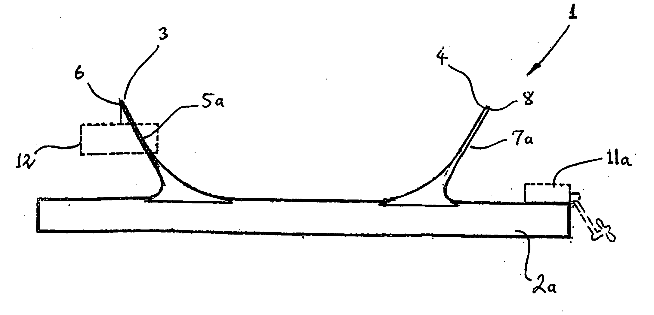
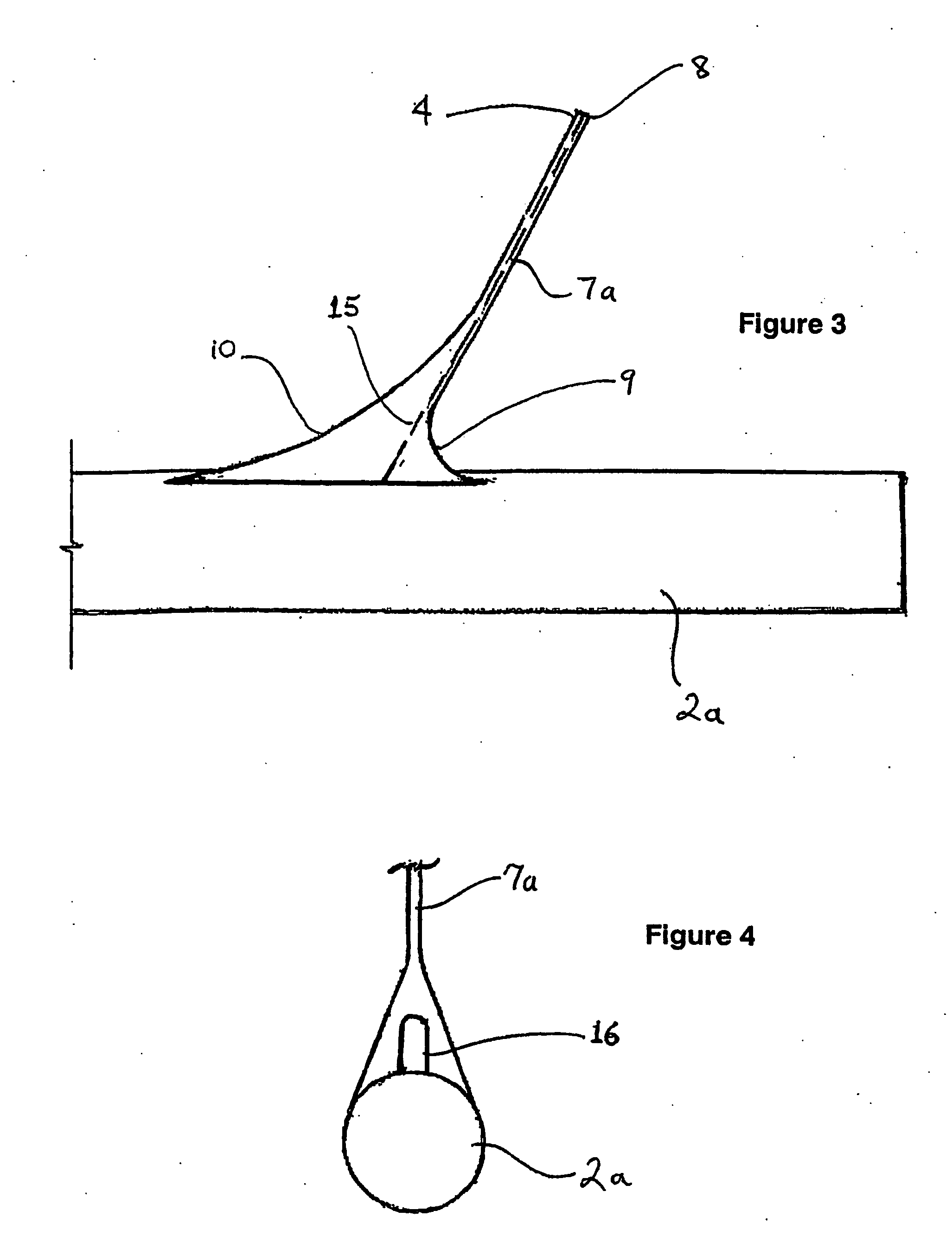
[0040]FIGS. 1 and 2 show a vessel 1 according to the invention. Vessel 1 has two hulls 2a and 2b of cylindrical form, with circular cross-section. Hulls 2a and 2b are secured to each other by connecting structures 3 and 4. Structure 3 has legs 5a and 5b respectively secured to hulls 2a and 2b, and an arch-shaped member 6 connecting upper ends of legs 5a and 5b. Structure 4 is similar, having legs, 7a and 7b, and a connecting member 8.

[0041] Structures 3 and 4 are substantially planar. As best seen in FIG. 1, the planes of structures 3 and 4 lie at an angle of 30 degrees from the vertical, the structures being furthest apart at their upper ends. It is emphasized that this particular arrangement of the connecting structures is optional. Arranging the two structures 3 and 4 in non-parallel planes assists in obtaining appropriate and adequate stability, stiffness and strength and a good distribution of forces without excessive weight.

[0042] The hydrodynamic forces generated by waves a...


PUM


Abstract

A cargo carrying nautical vessel (1) is provided, having a plurality of cargo carrying hulls (2a, 2b) connected by at least two connecting structures (3, 4), each connecting structure including legs (5a, 5b, 7a, 7b) of which each is upstanding from a hull and substantially rigidly connected thereto. The connecting structures (3, 4) include flexible sections whereby the hulls (2a, 2b) are to a predetermined extent capable of movement relative to each other. Such movement is provided to reduce the stresses and strains associated with movement in a seaway. Relative movement of the hulls (2a, 2b) is permitted by deflection of the connecting structures (3, 4), a majority of the deflection in each connecting structure occuring remotely from points of connection between said legs (5a, 5b, 7a, 7b) and said hulls. The vessel (1) is intended to be of comparatively low structural weight, draft and cost for its load capacity and particularly well suited to accessing small ports.

Description

TECHNICAL FIELD [0001] The present invention relates to a multi-hulled nautical vessel. In partlular, the present invention relates to the connection of hulls in a multi-hulled vessel. BACKGROUND ART [0002] Multi-hulled vessels usually have better maneuverability and a shallower draft than single hulled vessels. However, multi-hulled vessels are not commonly used to transport cargo, particularly across open water where rougher conditions can be experienced. Larger known mult-hulled vessels have the problem that in rough conditions, there can be excessive stress placed on the connections between the hulls, as well as on the hulls themselves, leading to fatigue if the connections are inadequate or requiring additional structural weight to avoid fatigue. [0003] In the transport of bulk liquids, such as liquefied petroleum gas (LPG) or liquid chemicals, it is usual to use large single hulled vessels. These vessels offer an efficient means to hold large quantities of fluid and do not suf...

Claims


Application Information

Patent Timeline
Patent Type & Authority Applications(United States)
IPC IPC(8): B63B1/14
CPCB63B1/14
Inventor VAN DIJK, JAC W
Owner VAN DIJK JAC W
Learn More