Gas storage tank and method of manufacturing the same

a technology of gas storage tank and gas absorbing/adsorption capacity, which is applied in the direction of heat treatment apparatus, packaged goods type, application, etc., can solve the problems of reducing the gas absorbing/adsorption capacity, the difficulty of drying up the wet absorbent/adsorbent,

Inactive Publication Date: 2005-01-06
TOYOTA JIDOSHA KK +1
View PDF6 Cites 57 Cited by
  • Summary
  • Abstract
  • Description
  • Claims
  • Application Information

AI Technical Summary

Benefits of technology

[0006] The object of the invention is to eliminate the drawbacks of the prior art technique and to provide a technique of manufacturing a gas

Problems solved by technology

It is extremely difficult to dry up the wet absorbent/adsorbent after packing in the filling

Method used


Image

  • Gas storage tank and method of manufacturing the same
  • Gas storage tank and method of manufacturing the same
  • Gas storage tank and method of manufacturing the same

Examples


first embodiment

[0052] First Embodiment

[0053] Structure of Hydrogen Storage Tank 10

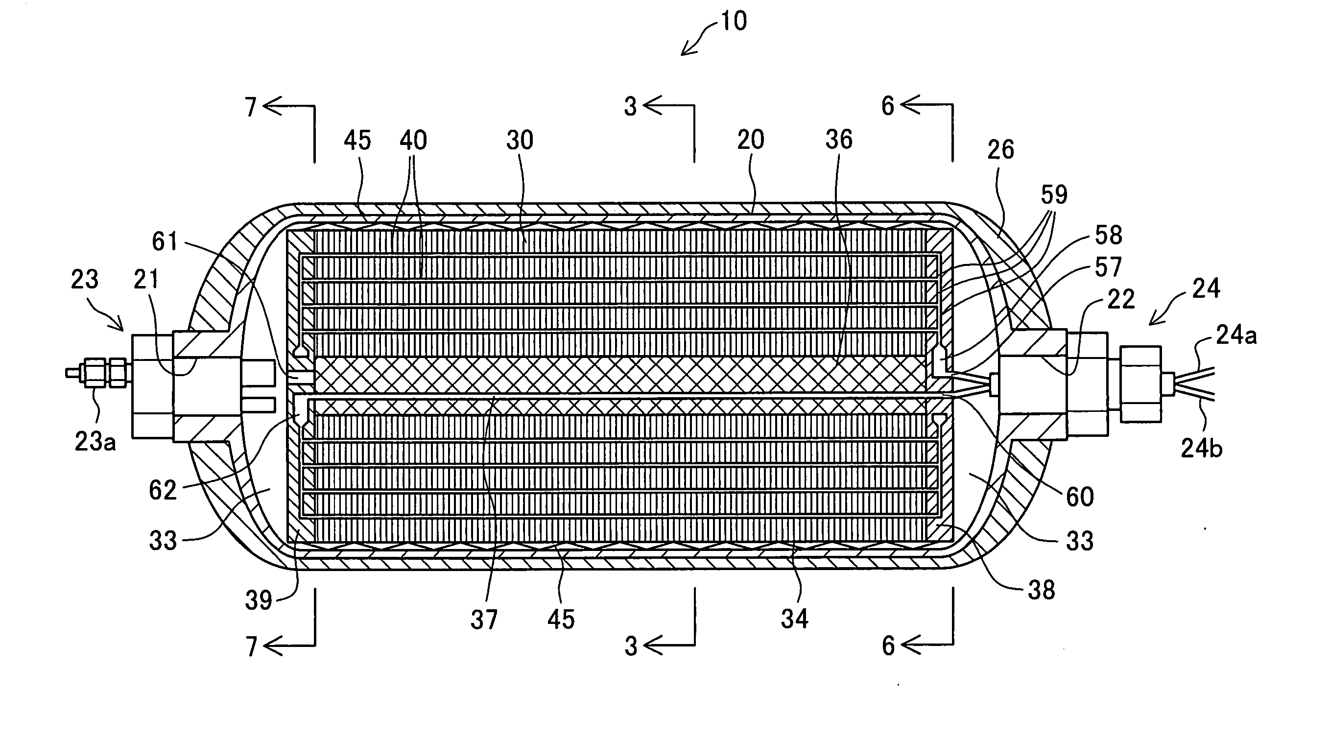
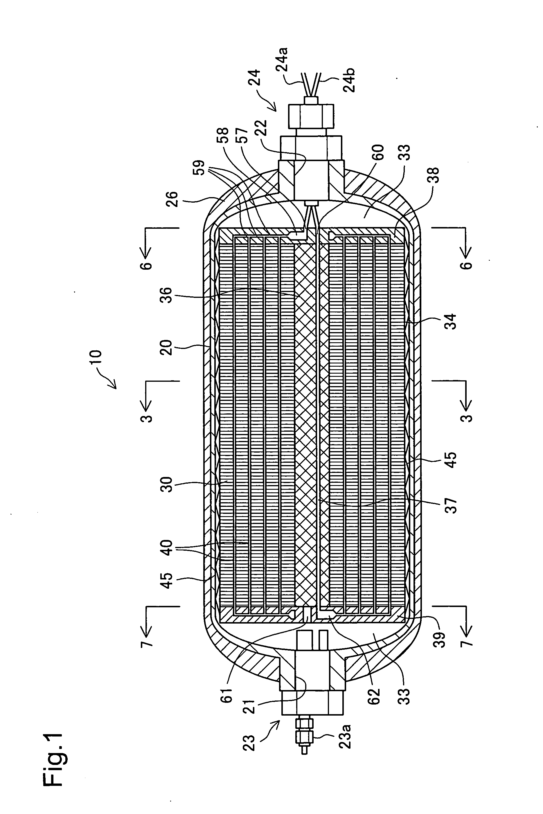
[0054]FIG. 1 is a vertical sectional view schematically illustrating the internal structure of a hydrogen storage tank 10 in a first embodiment of the invention. The hydrogen storage tank 10 includes a tank container 20 and a heat exchanger unit 30 located inside the tank container 20.

[0055] The tank container 20 functions as an outer wall member of the hydrogen storage tank 10 and is defined by a quasi-cylindrical hollow vessel. In the structure of this embodiment, the tank container 20 is made of an aluminum alloy. The tank container 20 has joint openings 21 and 22 on both ends thereof, which have smaller virtually-circular cross sections than the center cross section of the tank container 20. Joint assemblies 23 and 24 are set in the respective joint openings 21 and 22. The joint assemblies 23 and 24 form the structure of keeping the sufficient airtightness of the tank container 20 at the joint openings 21 and 22...

second embodiment

[0088] Second Embodiment

[0089] Structure of Hydrogen Storage Tank 110

[0090]FIG. 10 schematically illustrates the structure of a hydrogen storage tank 110 in a second embodiment of the invention. FIG. 11 is a sectional view of the hydrogen storage tank 110, taken on the line 11-11 in FIG. 10. The hydrogen storage tank 110 includes a tank container 120, a heat exchanger unit 130 located in the tank container 120, and a support member 140 interposed between the tank container 120 and the heat exchanger unit 130.

[0091] The tank container 120 is a quasi-cylindrical hollow vessel and is made of an aluminum alloy in this embodiment. The tank container 120 has joint openings 121 and 122 on both ends thereof, which have smaller virtually-circular cross sections than the center cross section of the tank container 120.

[0092] Joint assemblies 123 and 124 are set in the respective joint openings 121 and 122. The joint assemblies 123 and 124 form the structure of keeping the sufficient airtight...


PUM

PropertyMeasurementUnit
Areaaaaaaaaaaa

Abstract

The technique of the invention manufactures a gas storage tank, which includes a gas absorbent/adsorbent and is capable of storing a high-pressure gas. The manufacturing process of a hydrogen storage tank first assembles a heat exchanger unit and packs the particles of hydrogen storage alloy into the heat exchanger unit. The manufacturing process then blocks hydrogen storage alloy filling holes used for packing the hydrogen storage alloy in the heat exchanger unit and attaches a detachable cover member to a hydrogen inlet. The manufacturing process subsequently locates the heat exchange unit filled with the hydrogen storage alloy in a cylindrical tank and narrows both ends of the tank to form joint openings. The manufacturing process then heat-treating the tank under water cooling and detaches the cover member. The manufacturing process attaches joint assemblies to the joint openings and forms a reinforcement layer around the outer circumference of the tank to complete the hydrogen storage tank.

Description

BACKGROUND OF THE INVENTION [0001] 1. Field of the Invention [0002] The present invention relates to a gas storage tank for storing gas therein and a method of manufacturing such a gas storage tank. [0003] 2. Description of the Related Art [0004] Various gas storage tanks have been proposed to store a gas. One known method for storage of a gas is absorption or adsorption of the gas in a selected gas absorbent / adsorbent. One example is a hydrogen storage tank including hydrogen storage alloy. The hydrogen storage tank includes, for example, a cylindrical container that is filled with the hydrogen storage alloy and has one or two opening ends sealed by a flange. [0005] In the gas storage tank containing the gas absorbent / adsorbent, an increase in gas supply pressure to the gas storage tank accelerates absorption or adsorption of the gas. The increase in gas supply pressure to the gas storage tank enables a larger quantity of the gas to be stored in a compressed form in cavities formed...

Claims


Application Information

Patent Timeline
IPC IPC(8): F02B43/08F17C11/00
CPCC01B3/0005F17C11/005Y02E60/321Y10T29/4981Y10T29/4935Y10T29/49879Y02E60/324Y02E60/32F17C11/00
Inventor KIMBARA, MASAHIKOMORI, DAIGORONITO, TAKEHIROKUBO, HIDEHITOKUMANO, AKIKOTSUZUKI, MAKOTOISOGAI, YOSHIHIRO
Owner TOYOTA JIDOSHA KK
Why Eureka
Try Eureka