
Technique to fill silencers

a technology of silencer and filling machine, which is applied in the field of filling machine, can solve the problems of limited or the sections which are difficult to fill using the current technology, and limit the filling of the interior of the muffler

Inactive Publication Date: 2005-01-06
OWENS CORNING COMPOSITES SPRL BELGIUM
View PDF16 Cites 34 Cited by
  • Summary
  • Abstract
  • Description
  • Claims
  • Application Information

AI Technical Summary

Benefits of technology

"The present invention provides a process for filling odd-shaped silencers without having to build an entire muffler cavity where the fibers should be placed in their final stage. The process involves feeding fibrous material into a cavity formed between a muffler insert and a tool, compressing the wool to the muffler inserts, winding yarn around the fibrous material, and retrieving the filled insert from the tool. The invention also provides a process for introducing a fiber-encased blank into applications requiring a fiber-encased blank that expands after a first temperature peak. The technical effects of the invention include improved efficiency in the production of mufflers and reduced costs of raw materials used for acoustical purposes."

Problems solved by technology

While the technology of Ingemansson et al. improved many aspects of muffler technology, it does have certain drawbacks.
For example, the filling of the interior of the muffler, or sections of the interior of the muffler, is typically limited to certain geometries.
Thus, for example, mufflers having odd shapes, such as clamshell mufflers, are difficult to fill using the current technology.
As stated above, this thus limits the filling of the sections of the interior of the muffler due to space constraints and other considerations.

Method used


Image

  • Technique to fill silencers
  • Technique to fill silencers
  • Technique to fill silencers

Examples


Embodiment Construction

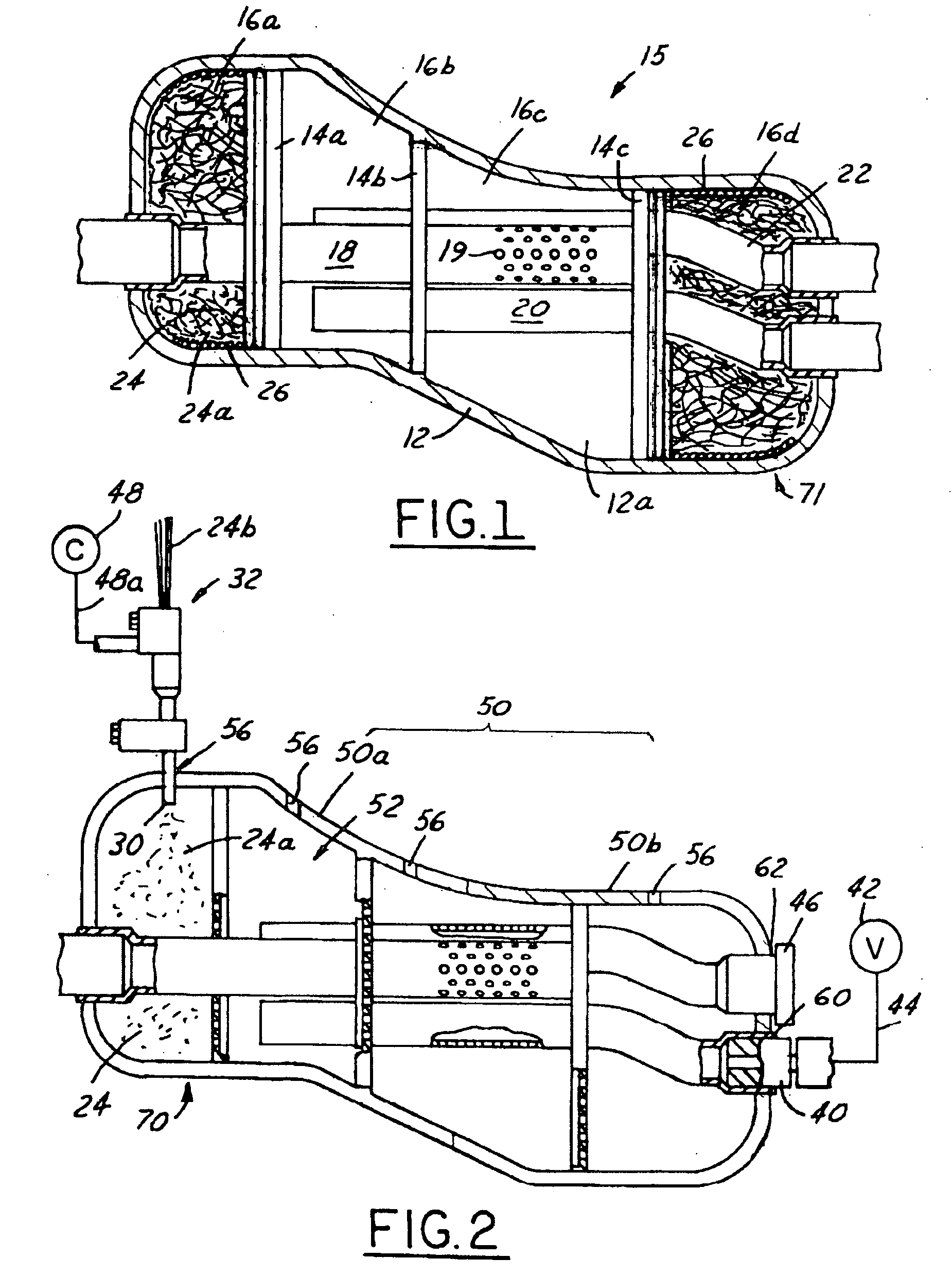
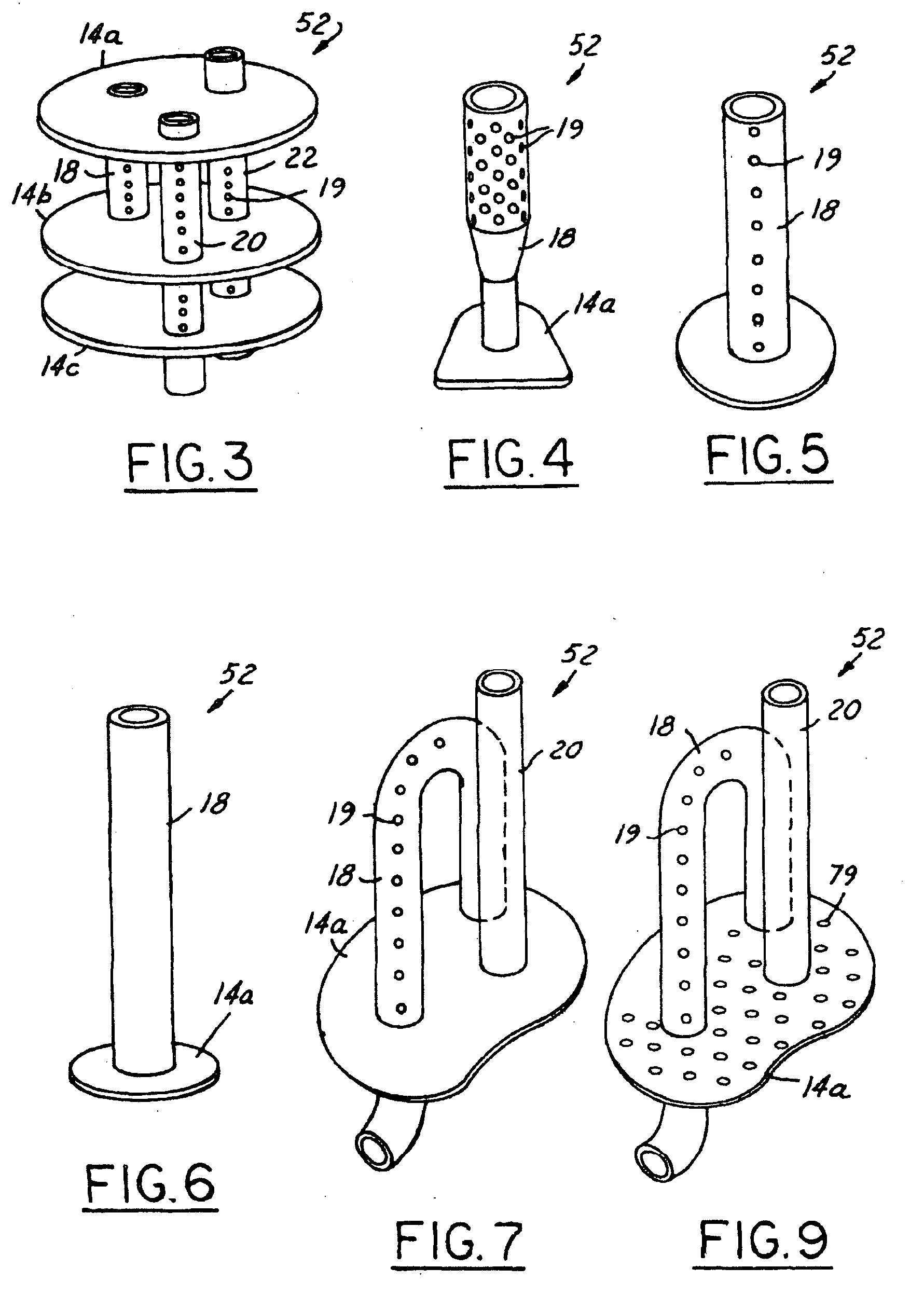
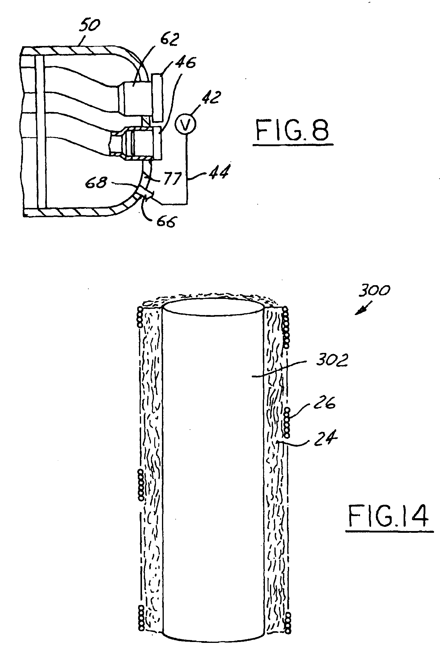
[0023] A process is provided for filling a muffler with fibrous material. Mufflers filled in accordance with the present invention are capable of being incorporated into vehicle exhaust systems and function as acoustic energy dissipaters (sound dampeners). Referring now to FIG. 1, a muffler 15 is illustrated which is capable of being filled in accordance with a first embodiment of the present invention. The muffler 15 comprises a closed outer shell 12 having first, second and third partitions 14a-14c which define first, second, third and fourth internal compartments 16a-16d of an inner cavity 12a within the muffler shell 12. A “closed muffler shell” as used herein means a single element muffler shell or a shell formed from two or more elements which are welded or otherwise coupled together such that they are not intended to be opened after introduction of a fibrous filling material 24. The muffler 15 further comprises first, second and third perforated pipes 18, 20 and 22. In the il...


PUM

PropertyMeasurementUnit
tensile strengthaaaaaaaaaa
temperaturesaaaaaaaaaa
tensile strengthaaaaaaaaaa

Abstract

A method for forming odd-shaped mufflers is achieved by first introducing an unfilled muffler insert having a desired number of pipes and partitions within a two-piece shaped tool. Fibrous material is introduced within desired compartments formed between the shaped tool and unfilled insert to form a filled insert. The shaped tool and filled insert are then placed on a winding device. A yarn thread is then wound and secured around the fibrous material within a gap created between the two pieces of the shaped tool. The winding device and shaped tool are then removed from the filled and wound muffler insert. The wound and filled muffler insert may then either be pressed into a previously formed muffler shell, or alternatively, the muffler shell may be formed around the wound and filled muffler insert to form the muffler.

Description

TECHNICAL FIELD AND INDUSTRIAL APPLICABILITY OF THE INVENTION [0001] This invention relates to a process for filling a silencer with fibrous material as well as a silencer filled with fibrous material. BACKGROUND OF THE INVENTION [0002] U.S. Pat. No. 4,569,471 to Ingemansson et al. describes a process and apparatus for feeding lengths of a continuous glass fiber strand into a muffler outer shell. The apparatus includes a nozzle for expanding the fiber strand into a wool-like material before the material enters the outer shell. In a first embodiment, filling of an outer cylinder of the muffler shell occurs without an end-piece joined to the outer cylinder. After the filling operation is completed, the outer cylinder is moved to a separate station where the end piece is welded onto the outer cylinder. During movement of outer cylinder, a vacuum device may remain coupled to the outer cylinder or a cover is placed over the filled outer cylinder so as to prevent the wool-like material fr...

Claims


Application Information

Patent Timeline
Patent Type & Authority Applications(United States)
IPC IPC(8): F01N1/24
CPCD04H1/4266D04H3/073D04H5/10F01N1/04Y10T29/49398F01N2310/02F01N2450/06F01N2490/155F01N1/24
Inventor BRANDT, LUCCARON, JEAN-PIERRE
Owner OWENS CORNING COMPOSITES SPRL BELGIUM
Learn More