Method for the linearization of FMCW radar devices

a radar device and linearization technology, applied in the direction of measurement devices, radio wave reradiation/reflection, using reradiation, etc., can solve the problems of large construction effort, phase errors in reception signals, loss of signal evaluation accuracy, etc., to reduce the scanning cycle ta, easy to implement, and low cost

Inactive Publication Date: 2005-01-06
AIRBUS DEFENCE & SPACE
View PDF6 Cites 40 Cited by
  • Summary
  • Abstract
  • Description
  • Claims
  • Application Information

AI Technical Summary

Benefits of technology

Another advantage of the invention is that there can be in an inexpensive estimation method that can be easily implemented, since the reception signal is processed in the base band. This signal results in a reduction of the scanning cycle TA by a factor K between 30 and 60. In addition another advantage of this method is that there can be a calculation of the polynomial coefficients via a robust estimation method. This is even in the case of channels subject to severe interference. Thus, there can be a relatively good compensation of phase errors with signal to noise ratios (SNR) of up to −20 dB using this method. Thus, the method can be used for not only the civil sector, but also in the military sector or for distance measurements.

Problems solved by technology

With FMCW radar devices, phase errors occur in the reception signal, as the result of a not strictly linear characteristic in a transmission frequency of an FMCW radar device.
This results in a loss of accuracy in the evaluation of the signal.
In particular, the disadvantages of this method are the great amount of construction effort, expense and the age-related clouding of the optical components.
However, a disadvantage of this system is that there is a large construction effort and expense associated with this cost intensive structure.
A disadvantage of this system is that this involves a great construction effort, which is cost intensive, since additional components are required.

Method used


Image

  • Method for the linearization of FMCW radar devices
  • Method for the linearization of FMCW radar devices
  • Method for the linearization of FMCW radar devices

Examples


Embodiment Construction

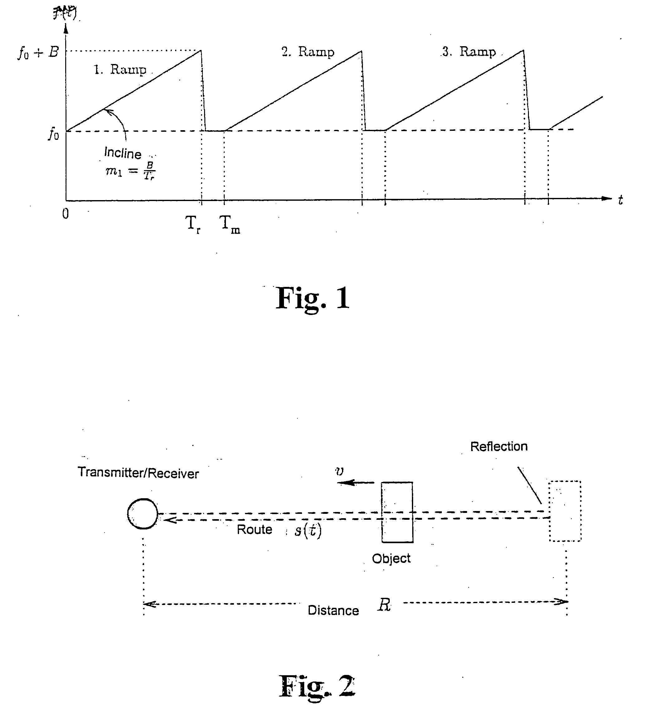
Turning now in detail to the drawings, FIG. 1 shows the starting point of this method is the transmission signal of an FMCW radar that is in the general polynomial approach of the Nth order for a transmission ramp as: x⁡(t)=exp⁢{j2π⁡(fo⁢t+m12⁢t2+m23⁢t3+m24⁢t4+…+γ0)}(1)

With t ε[0,Tr]. With this design, the coefficients ml with l=2, . . . ,N represent the polynomial parameters, γo represents the initial phase, and Tr represents the time duration of the transmission ramp. The parameter m1 or slope that is assumed to be given, indicates the linear component m1=B / t, which is exclusively present in an ideal case, wherein B describes the frequency deviation of the FMCW radar system. Thus in the following formula, a single reflecting point shaped object is assumed. Thus, the corresponding parameters are represented in FIG. 1, using the example of an idealized transmission signal. Thus with Equation (1) the reception signal in an ideal, noise free case is then: y⁡(t)=exp⁢{j2π⁡(fo⁢t+m12⁢t...


PUM


Abstract

A method for the linearization of frequency modulated continuous wave (FMCW) radar devices having non-linear, ramp-shaped, modulated transmitter frequency progression x(t). With this invention, a correction phase term for compensation of the phase error in the reception signal q(t) is calculated on the receiver side in this device.

Description

CROSS REFERENCE TO RELATED APPLICATIONS This application is based upon German Application Serial No. 10315012.9 Filed on Apr. 2, 2003 wherein priority is claimed under 35 U.S.C. 119. BACKGROUND OF THE INVENTION The invention relates to a method for the linearization of a frequency modulated continuous wave (FMCW) radar device. With FMCW radar devices, phase errors occur in the reception signal, as the result of a not strictly linear characteristic in a transmission frequency of an FMCW radar device. This results in a loss of accuracy in the evaluation of the signal. In this case, various methods are known for linearizing an FMCW radar device. For example, one known method discloses a method wherein a delayed transmission signal is generated via an optical delay line having a defined running time. In this case, the delayed transmission signal is mixed with the non-delayed transmission signal. Thus, it is possible to determine the deviation from the ideal linear characteristics. I...

Claims


Application Information

Patent Timeline
Patent Type & Authority Applications(United States)
IPC IPC(8): G01S7/35G01S7/40G01S13/34
CPCG01S7/352G01S2007/356G01S13/343G01S7/4021G01S7/354G01S7/356
Inventor KLIEWER, JORGWEISS, GEORG
Owner AIRBUS DEFENCE & SPACE
Why Eureka
Try Eureka