Anisotropic spectral scattering films, polarizers and liquid crystal displays

a polarizer and anisotropic spectral scattering technology, applied in the direction of instruments, optical waveguide light guides, optical light guides, etc., can solve the problems of low power consumption, the viewing angle characteristics of liquid crystal displays cannot exceed those of crts, and the stn liquid crystal displays using liquid crystal molecules with a twist angle of 180-270° cannot achieve high black and white contrast, etc., to achieve excellent color compensation function improve color viewing angle characteristics

Active Publication Date: 2005-01-06
FUJIFILM CORP
View PDF5 Cites 56 Cited by
  • Summary
  • Abstract
  • Description
  • Claims
  • Application Information

AI Technical Summary

Benefits of technology

An object of the present invention is to provide anisotropic spectral scattering films capable of independently improving color-viewing angle characteristics without impairing other characteristics such as contrast and viewing angle. Another object of the present invention is to provide polarizers having an excellent color compensation function and liquid crystal displays having improved color-viewing angle characteristics using said films.

Problems solved by technology

Recently, liquid crystal displays have widely replaced CRTs because they are thin and light and consume little power.
Thus, viewing angle characteristics of liquid crystal displays have not surpassed those of CRTs.
STN liquid crystal displays using liquid crystal molecules having a twist angle of 180-270° could not achieve high black and white contrast because the birefringence of the liquid crystal polymers resulted in coloration such as dark blue pixels on a yellow-green background.
This hue also caused a problem when images were displayed in color by such liquid crystal displays through color filters.
An approach to this problem was to improve hue by optical compensation and succeeded in color compensation using a retardation film (e.g., see Nikkei Microdevice, October 1987, page 84), but the color compensation was insufficient partially because the liquid crystal layer and the retardation film have different wavelength distributions at wavelengths other than a specific wavelength to be compensated completely.
Especially, optical compensation sheets based on a disc-shaped compound greatly improved the contrast-viewing angle characteristics of TN-LCDs so that they are widely used in commercially available TN-LCDs, but color shift with viewing angle have not been sufficiently improved.
However, contrast is also an important viewing angle characteristic of LCDs, and it is not easy to satisfy both color and contrast performances by using retardation films.
However, these films are aimed to control the path of white light but not to control spectral scattering characteristics at each viewing angle, and therefore, their color compensation effect is not complete.
As described above, color-viewing angle characteristics of LCDs could not be improved without impairing other characteristics by conventional color compensation techniques using retardation films or color filters.
Even if wide viewing angle LCD modes were used, the color-viewing angle characteristics were inferior to those of CRTs.

Method used


Image

  • Anisotropic spectral scattering films, polarizers and liquid crystal displays
  • Anisotropic spectral scattering films, polarizers and liquid crystal displays
  • Anisotropic spectral scattering films, polarizers and liquid crystal displays

Examples


first embodiment

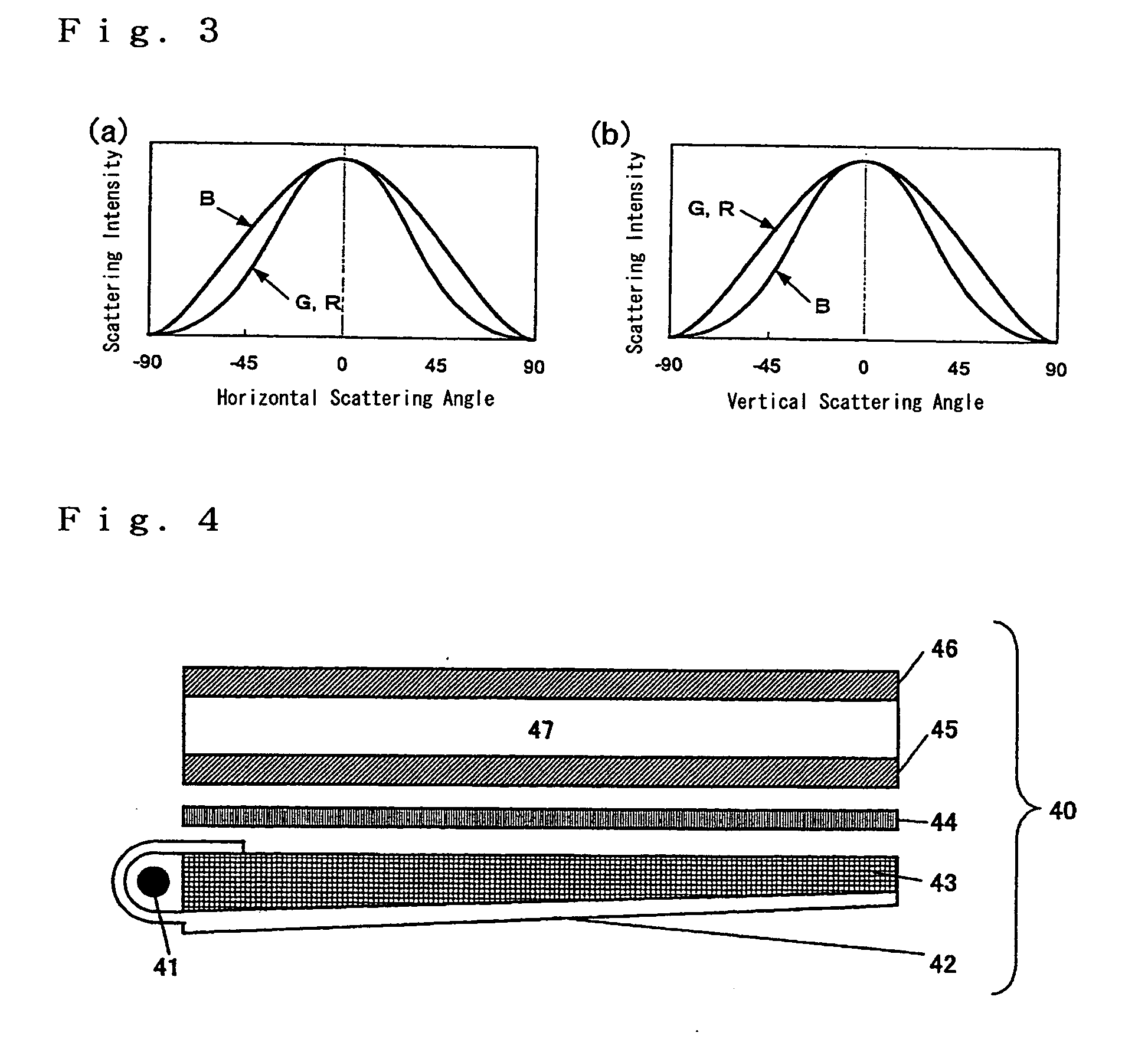
As used herein, the term “anisotropic spectral scattering film” means a film characterized by different scattered light distributions at two wavelengths arbitrarily selected from 435 nm (B) , 545 nm (G) and 610 nm (R) as well as different scattered light distributions between two scattering planes orthogonal to each other. an anisotropic spectral scattering film of the present invention is characterized in that the scattered light intensity Fx(λ,θ) at azimuthal angle θ and incident wavelength λ in an arbitrary scattering plane with respect to the film surface and the scattered light intensity Fy(λ, θ) at azimuthal angle θ and incident wavelength λ in a scattering plane orthogonal to said scattering plane satisfy the following equations (1) and (2):

Fx(λ, θ) / Fx(545, θ)≧1.2   (1)

{Fx(λ, θ) / Fx(545, θ)−Fy(λ, θ) / Fy(545, θ)}≧0.1   (2)

provided that λ is 435 or 610 nm and θ is an arbitrary angle selected from 30 to 70°.

second embodiment

an anisotropic spectral scattering film of the present invention is characterized in that said Fx(λ, θ) and Fy(λ, θ) satisfy the following equation (3):

{Fx(λ, θ)) / Fx(545, θ)−1}{Fy(λ, θ) / Fy(545, θ)−1}<0.   (3)

The wavelengths 435 nm, 545 nm and 610 nm are typical of B, G and R, respectively. In the present invention, the wavelength λ may be within a tolerance of ±10 nm.

In equation (1) above, Fx(80 , θ) / Fx(545, θ) is preferably 1.2 to 5.0, more preferably 1.5 to 3.5. In equation (2) above, {Fx(λ, θ) / Fx(545, θ) −Fy(λ, θ) / Fy(545, θ)} is preferably 0.1 to 5.0, more preferably 0.5 to 3.0. In equation (3) above, {Fx(λ, θ) / Fx(545, θ)−1}{Fy(λ, θ)) / Fy(545, θ)−1} is preferably −5.0 to −0.1, more preferably −3.0 to −0.3.

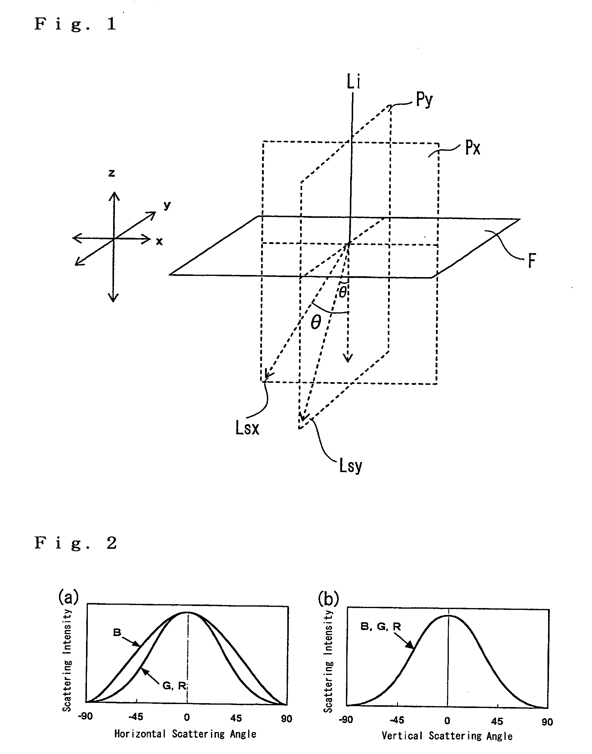
Referring to FIG. 1, a method for evaluating the wavelength dependency and anisotropy of the scattered light distribution of a film is explained.

Light Li at wavelength λ is incident on film F from above. The incident light Li is scattered into various directions (e.g...

examples

The following examples further illustrate the present invention. The materials, reagents, amounts and proportions thereof, procedures or the like shown in the following examples can be appropriately changed without departing from the spirit of the present invention. Therefore, the scope of the present invention is not limited to the specific examples shown below.

(Preparation of an Anisotropic Spectral Scattering Film AS-1)

A holographic photopolymer (OmniDex HRF-352 from DuPont) was spin-coated to a thickness of 9 μm on a polyethylene terephthalate film and exposed to a two-beam interference system at a dose of 75 mJ / cm2 using an argon laser at 488 nm. Then, the coating film was irradiated with UV light at an irradiance of 400 mW / cm2 and a dose of 300 mJ / cm2 using a 160 W / cm air-cooled metal halide lamp (from Eye Graphics Co., Ltd.) and then dried at 100° C. for 1 hour to prepare an anisotropic spectral scattering film AS-1 based on a one-dimensional diffraction grating.

(Prepa...


PUM

PropertyMeasurementUnit
refractive indexaaaaaaaaaa
twist angleaaaaaaaaaa

Abstract

A novel anisotropic spectral scattering film is disclosed. The scattered light intensity Fx(λ, θ) at azimuthal angle θ and incident wavelength λ in an arbitrary scattering plane with respect to a surface of the film, and the scattered light intensity Fy(λ,θ) at azimuthal angle θ and incident wavelength λ in a scattering plane orthogonal to said scattering plane satisfy the following equations (1) and (2):
Fx(λ, θ)/Fx(545, θ)≧1.2   (1)
{Fx(λ, θ)/Fx(545, θ)−Fy(λ, θ)/Fy(545, θ)}≧0.1   (2)
provided that λ is 435 or 610 nm and θ is an arbitrary angle selected from 30-70°.

Description

BACKGROUND OF THE INVENTION 1. Field of the Invention The present invention relates to scattering films having wavelength dependency in scattered light distribution and anisotropy in scattered light distributions between the vertical and horizontal directions as well as polarizers and liquid crystal displays using said films. 2. Description of Related Art Previously, CRTs (Cathode Ray Tubes) have been mainly used for displays in office automation equipments such as word processors, notebook computers and monitors for personal computers, mobile terminals and televisions. Recently, liquid crystal displays have widely replaced CRTs because they are thin and light and consume little power. Liquid crystal displays comprise a liquid crystal cell and a polarizer. The polarizer, which usually consists of a protecting film and a polarizing film, is obtained by dyeing a polarizing film formed of a polyvinyl alcohol film with iodine and stretching it and then laminating a protecting film o...

Claims


Application Information

Patent Timeline
Patent Type & Authority Applications(United States)
IPC IPC(8): F21V8/00G02B5/02G02B6/10G02F1/1335
CPCG02B5/0215G02B5/0242G02B5/0252G02F1/133504G02B5/0294G02B6/0051G02B6/105G02B5/0257
Inventor AMIMORI, ICHIROFUJIWARA, ISAO
Owner FUJIFILM CORP
Why Eureka
Try Eureka