Image processing system, projector, program, information storage medium, and image processing method
Inactive Publication Date: 2005-01-06
SEIKO EPSON CORP
View PDF1 Cites 33 Cited by
Summary
Abstract
Description
Claims
Application Information
AI Technical Summary
This helps you quickly interpret patents by identifying the three key elements:
Problems solved by technology
Method used
Benefits of technology
Benefits of technology
[0011] The present invention was devised in light of the above-described technical problems. The present invention may prove an image processingsystem, a projector, a program, an information storage medium, and an image processing method that make it possible to reproduce image colors appropriately, by reducing the effects of ambient light and time-related deterioration, and, in particular, to provide an image processing system, a projector, a program, an information storage medium, and an image processing method that make it possible to reproduce image colors appropriately even when used for long periods of time.
Problems solved by technology
When an image is displayed for a long time by an image display device such as a projector, color non-uniformity (including color non-uniformity due to luminance non-uniformity) are created in the image and the image gradually deteriorates.
In such a case, the original display effect could be lost due to deterioration of components such as the liquid-crystal panel or a polarization plate during projection over a long period of time, which could generate color non-uniformity in the image.
Causes of color non-uniformity due to time-related deterioration include the occurrence of light deficiencies due to time-related deterioration in a liquid-crystallight valve or polarization plate.
However, if color non-uniformity occurs in the black monochromatic calibration image itself, it is possible that appropriate color correction cannot be applied because the above-described differential values are not accurate.
Method used
Image
Click on the blue label to locate the original text in one second.
Reading with bidirectional positioning of images and text.
Examples
first embodiment
[0166] First Embodiment
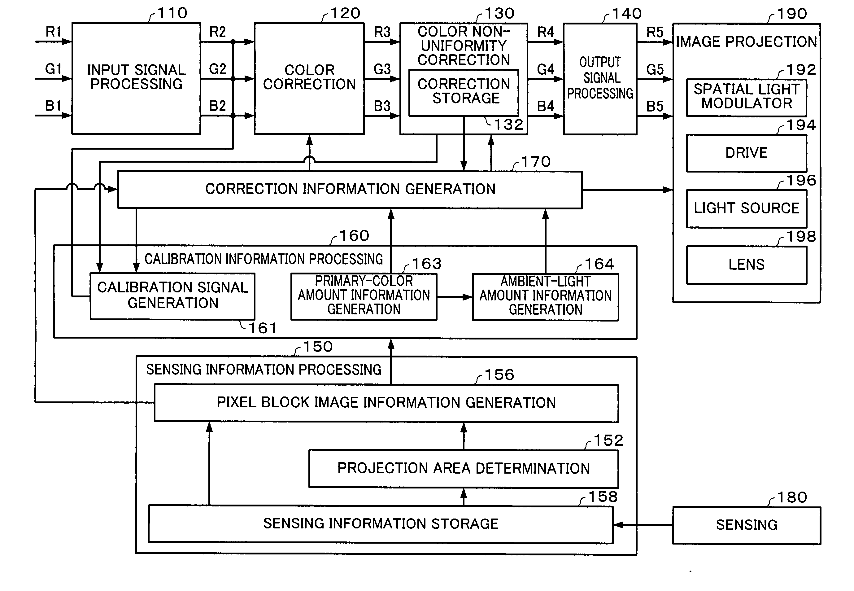
[0167] A schematic view of the image projection state of a first embodiment of the present invention is shown in FIG. 1.
[0168] A projector 20 projects an image towards a screen 10. This causes the formation of a projection area 12 that is an image display area in the screen 10.
[0169] If an image display device such as the projector 20 is used for displaying an image for a long period of time, time-related deterioration in components such as the optical system will gradually generate color non-uniformity (including color non-uniformity due to luminance non-uniformity) in the image.
[0170] On top of that, the effects of ambient light 80 such as daylight or artificial lighting will change the way in which the image in the projection area 12 is seen. In other words, the way in which the image is seen is affected not only by time-related deterioration but also by the actual display state thereof.
[0171] To correct such color non-uniformity in the image, the proje...
second embodiment
[0218] Second Embodiment
[0219] The description now turns to a method of obtaining the amount of ambient light without using a black calibration image, that differs from the method of the previous embodiment.
[0220] A functional block diagram of a projector in accordance with this second embodiment is shown in FIG. 5.
[0221] A calibration information processing section 260 within a projector of this embodiment comprises a calibration signal generation section 261 that generates a calibration signal for displaying a first calibration image and a calibration signal for displaying a second calibration image having RGB values in the same ratios as those of the first calibration image.
[0222] The calibration information processing section 260 also comprises a display color information generation section 263 that calculates a differential image signal value between a sensing signal value for the first calibration image and a sensing signal value for the second calibration image and also a ...
third embodiment
[0235] Third Embodiment
[0236] The description now turns to an embodiment in which the correction of color non-uniformity is based on the light-deficiency amount of primary colors.
[0237] In this embodiment, the projector 20 projects a monochromatic calibration image (one in which the entire image is a uniform color) in the Y-family colors, the M-family colors, and the C-family colors. Note that, in this case, Y-family colors are colors that have RGB values of (255, 255, m), M-family colors are colors that have RGB values of (255, m, 255) and C-family colors have RGB values of (m, 255, 255). In this case, m is any integer from 0 to 255, when colors are represented as 8-bit values, by way of example.
[0238] While projecting these images, the projector 20 increments the value of m sequentially from 0 by a predetermined amount (such as from 1 to 32), where m is the B-value for the Y-family colors, by way of example. It does the same for the M-family colors and B-family colors too. It sh...
PUM
Abstract
In order to provide an image processingsystem and the like that can reproduce colors more appropriately, a projector is provided with a calibration signal generation section that generates a calibration signal for a white image and calibration signals for three subtracted-primary-color images, each of which is obtained by subtracting a predetermined input value from the RGB values of a predetermined primary color, one of plurality of kinds of primary colors that together form white; an image projection section for displaying each calibration image, based on the corresponding calibration signal; a sensing section for sensing each displayed calibration image; a primary-color amount information generation section for calculating a difference between sensing signal values and calculating an image signal value for the highest output value of each of the RGB colors, based on that difference; an ambient-light amount information generation section for calculating an ambient-light amount based on differences between image signal values; and a correction information generation section for generating correction information for applying corrections, based on the highest output value for each of the RGB colors and the ambient-light amount.
Description
[0001] Japanese Patent Application No. 2003-138173, filed on May 16, 2003, and Japanese Patent Application No. 2003-150850, filed on May 28, 2003, are hereby incorporated by reference in their entirety. BACKGROUND OF THE INVENTION [0002] The present invention relates to an image processingsystem, a projector, a program, an information storage medium, and an image processing method. [0003] When an image is displayed for a long time by an image display device such as a projector, color non-uniformity (including color non-uniformity due to luminance non-uniformity) are created in the image and the image gradually deteriorates. [0004] This could happen when a projector is used to display an image continuously on a screen in a store or exhibition hall, for example. In such a case, the original display effect could be lost due to deterioration of components such as the liquid-crystal panel or a polarization plate during projection over a long period of time, which could generate color no...
Claims
Application Information
Patent Timeline
Application Date:The date an application was filed.
Publication Date:The date a patent or application was officially published.
First Publication Date:The earliest publication date of a patent with the same application number.
Issue Date:Publication date of the patent grant document.
PCT Entry Date:The Entry date of PCT National Phase.
Estimated Expiry Date:The statutory expiry date of a patent right according to the Patent Law, and it is the longest term of protection that the patent right can achieve without the termination of the patent right due to other reasons(Term extension factor has been taken into account ).
Invalid Date:Actual expiry date is based on effective date or publication date of legal transaction data of invalid patent.

