Projection type image display apparatus

a projection type, image display technology, applied in the direction of picture reproducers, instruments, printers, etc., can solve the problem of taking time to harden the adhesively fixed portion, and achieve the effect of high reliability, excellent repair and maintenance characteristics, and high reliability

Active Publication Date: 2005-01-06
MAXELL HLDG LTD
View PDF1 Cites 10 Cited by
  • Summary
  • Abstract
  • Description
  • Claims
  • Application Information

AI Technical Summary

Benefits of technology

[0008] It is an object of the present invention to solve the above problems by providing a low-cost projection type image display apparatus having high reliability and excellent repair and maintenance characteristics. Particularly, it is an object of the present invention to realize adjustment and fixing of optical component of light guide means from an illumination unit to a liquid crystal panel simply with high reliability.
[0009] As means for solving the problems, according to the present invention, in adjustment of optical component constituting light guide means, a spring portion is provided in part of a holding member of the optical component. The spring portion of the holding member is bent and the optical component is temporarily held to a case of rigid body for holding the whole optical system by reaction force. After it is temporarily held, an adjustment mechanism provided outside of the apparatus is separated or removed and the holding member of the optical component is adhesively fixed to the case of the rigid body with much time spent. The adjustment time and the occupation time of the adjustment mechanism are shortened. The holding member of the optical component is made of thermoplastic high-molecule material and the holding member and the optical component are fixed to each other by welding to thereby hold the optical component stably with high reliability.

Problems solved by technology

In the prior arts disclosed in JP-A-2000-2932 and JP-A-2001-264726, it is not sufficiently recognized heretofore that the adjustment mechanism is complex and in the prior art disclosed in JP-A-2003-75696, it is not sufficiently recognized heretofore that it takes time to harden the adhesively fixed portion.

Method used


Image

  • Projection type image display apparatus
  • Projection type image display apparatus
  • Projection type image display apparatus

Examples


first embodiment

[0021] FIGS. 1 to 7 are diagrams for explaining a first embodiment according to the present invention. Description is made successively from FIGS. 1A and 1B.

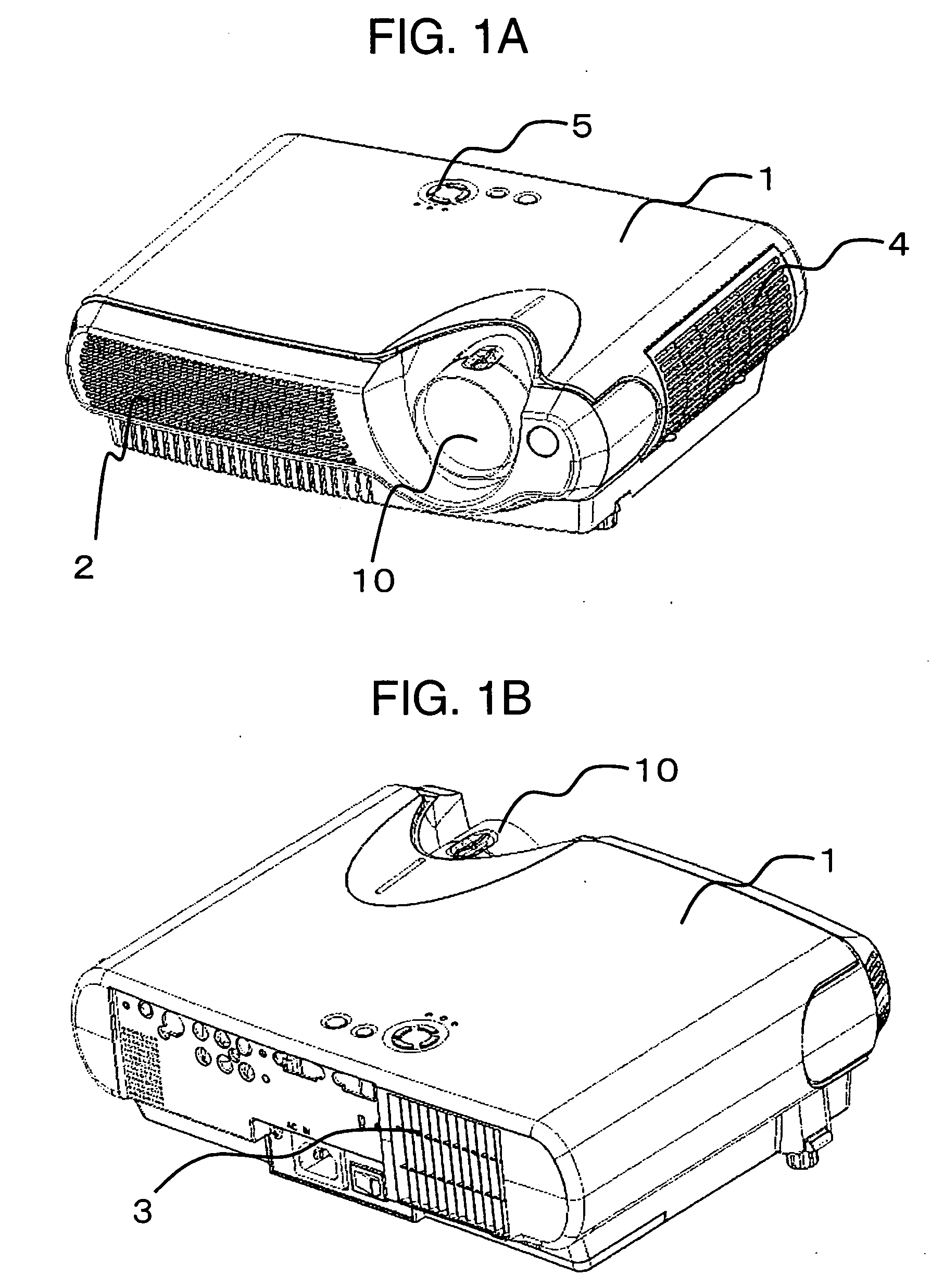
[0022]FIGS. 1A and 1B are perspective views showing the external appearance of a projection type image display apparatus of the first embodiment according to the present invention. FIG. 1A shows a front side of the projection type image display apparatus 1 and FIG. 1B shows a rear side of the projection type image display apparatus.

[0023] In FIGS. 1A and 1B, the projection type image display apparatus 1 of the present invention includes an exhaust port 2 disposed at the same side as a projection lens 10, that is, disposed at the front side thereof as shown in FIG. 1A and an intake port 3 disposed at the rear side as shown in FIG. 1B. Other elements including an operation button 5 and a panel intake port 4 are disposed at the exterior side of the apparatus 1.

[0024] The projection type image display apparatus 1 is operated by op...


PUM

PropertyMeasurementUnit
flexibilityaaaaaaaaaa
reaction forceaaaaaaaaaa
heat-melting aaaaaaaaaa

Abstract

Adjustment of the illumination range to a liquid crystal panel of a liquid crystal projector requires time in fixing upon adjustment and accordingly it is an object to make the adjustment effectively. In an adjustment mechanism of the illumination range of illumination means to the liquid crystal panel in an optical engine unit of the liquid projector, the spring property is provided in a lens holder for holding a lens and the lens is temporarily held by friction of the spring portion to the optical engine case after adjustment. Then, the adhesion processing is made to complete the adjustment.

Description

BACKGROUND OF THE INVENTION [0001] The present invention relates to a display apparatus for projecting an image on a screen by means of a light bulb element such as a liquid crystal panel and particularly to a projection type image display apparatus such as a liquid crystal projector apparatus and a rear projection type display apparatus. [0002] Heretofore, a projection type image display apparatus such as a liquid crystal projector and a rear projection type display apparatus is known in which light from a light source such as an electric bulb is intensity-modulated to be changed to shaded light in each pixel in accordance with an image signal by means of light bulb means such as a liquid crystal panel, so that an optical image is formed to be projected on a screen in enlarged manner. [0003] In a recent projection type image display apparatus, generally, light from light source means separated into a plurality of colors (e.g. three colors) by spectroscope means is modulated by ligh...

Claims


Application Information

Patent Timeline
Patent Type & Authority Applications(United States)
IPC IPC(8): G03B21/00G02F1/13G03B21/14H04N9/31
CPCH04N9/3141H04N9/3197H04N9/317
Inventor TSUBATA, FUSAMITSUUEOKA, KAZUMASASHIRAISHI, MIKIOMIURA, HIROTOHONDA, NOBUYUKI
Owner MAXELL HLDG LTD
Why Eureka
Try Eureka