Module for uniforming light

Inactive Publication Date: 2005-01-06
IND TECH RES INST
View PDF18 Cites 60 Cited by
  • Summary
  • Abstract
  • Description
  • Claims
  • Application Information

AI Technical Summary

Benefits of technology

[0012] According to the preferred embodiment of the present invention, the gapless microlens array is formed of a macromolecular transparent material, such as Polyimide (PI), Polymethyl Methacrylate (PMMA) and Polycarbonate (PC). The top view of the bugle can be a hexagon, a square, a polygon or a combined structure. The gapless microlens array replaces the conventional diffusion sheet or brightness enhancement film. However, the diffusion sheet or the brightness enhancement film also can be assembled on the back l

Problems solved by technology

This structure can cause a situation where the light is absorbed and refle

Method used


Image

  • Module for uniforming light
  • Module for uniforming light
  • Module for uniforming light

Examples


Example

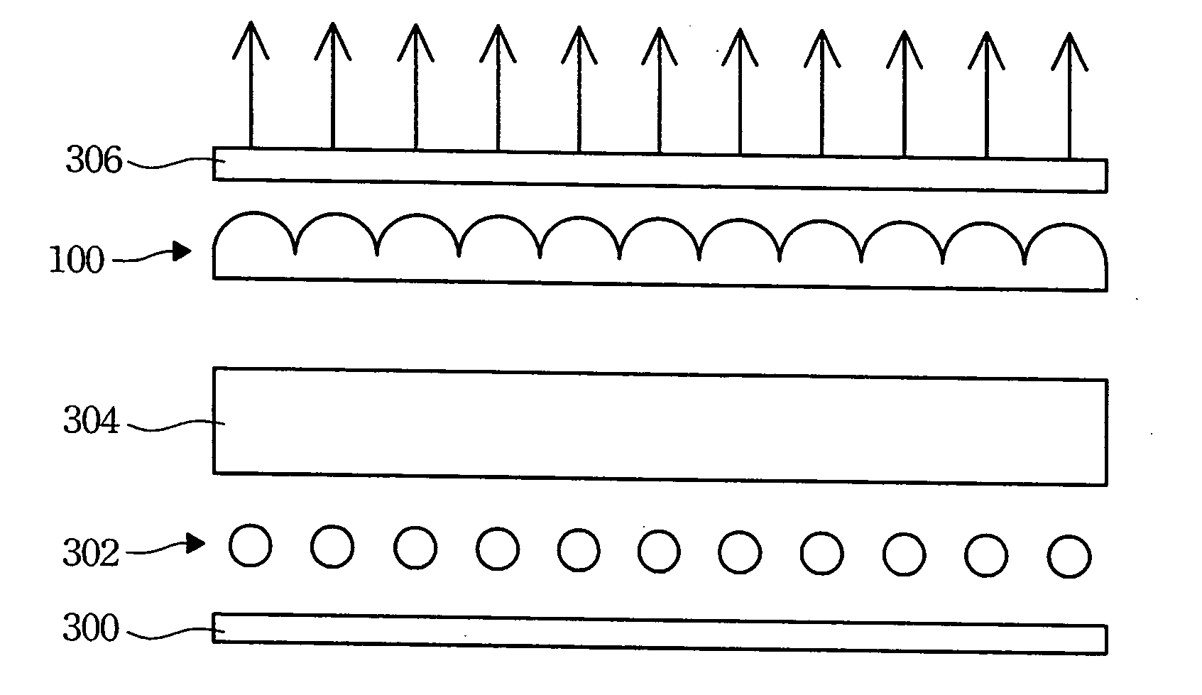
[0022] The present invention provides a uniform light module with one or more one gapless microlens array.

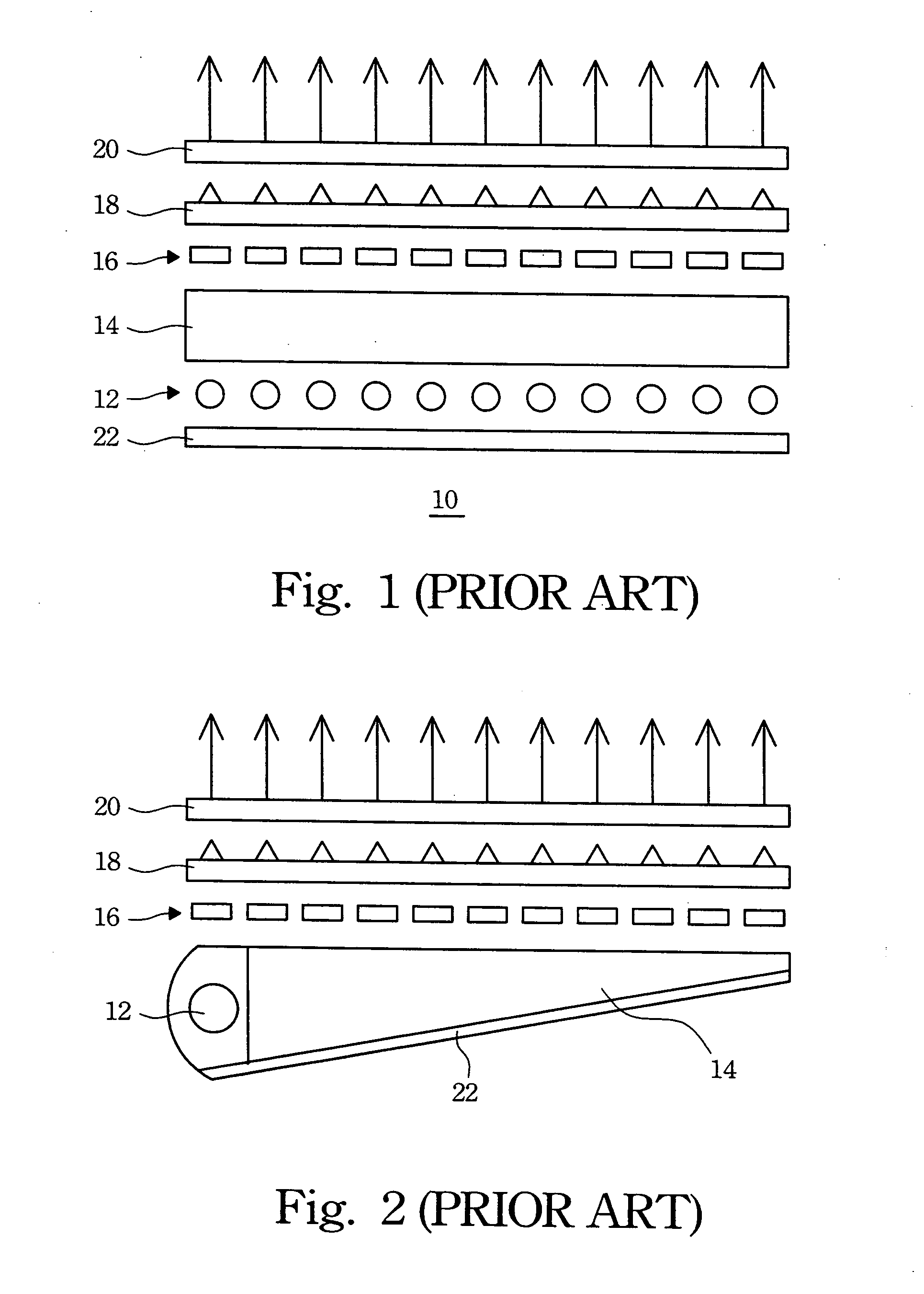
[0023] Microlenses are widely used in the optical fiber, optical communication and optical electrical products. For example, a microlens is assembled in the end terminal of the optical fiber to collect light. However, some gaps exist between the microlens of the microlens array, which can affect the dots per inch.

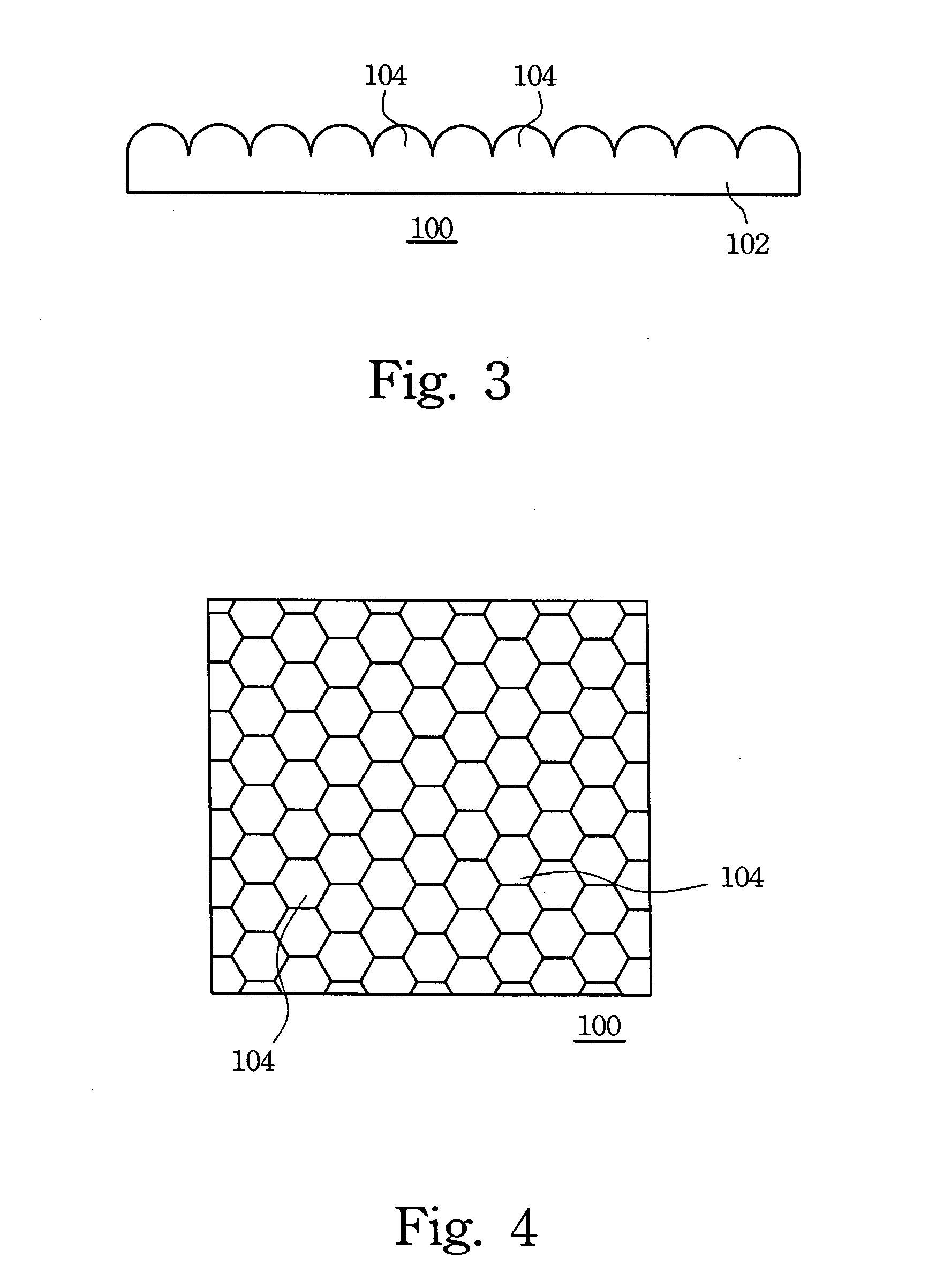
[0024] Therefore, the present invention uses a gapless microlens array to solve the above problem. FIG. 3 illustrates a cross-sectional diagram of the gapless microlens array of the present invention. Referring to FIG. 3, the gapless microlens array 100 of the present invention comprises a substrate 102 and a plurality of bulges 104 located on the substrate 102. These bulges are connected together. In other words, there are no spaces between these bulges.

[0025] According to the preferred embodiment, the preferred cross-sectional view of the bulge 104 is a ball and si...


PUM


Abstract

A module for equalizing light in liquid crystal display, having a light source and at least one gapless microlens array, is described. The gapless microlens array has a substrate and a plurality of bumps located on the substrate, and the bumps are connected closely with each other so that there is no gap between the bumps. Light is gathered, equalized and diffused by using the gapless microlens array.

Description

FIELD OF THE INVENTION [0001] The present invention relates to a back light module of a panel, and more particularly to a module for equalizing light. BACKGROUND OF THE INVENTION [0002] User demand for entertainment equipment is particularly high as a result of the rapid development of multimedia applications. Conventionally, the cathode ray tube (CRT) display, which is a type of monitor, is commonly used. However, the cathode ray tube display does not meet the needs of multimedia technology because of the large volume thereof. Therefore, many flat panel display techniques such as liquid crystal display (LCD), plasma display panel (PDP), and field emission display (FED) have been recently developed. Of these techniques, the liquid crystal display (LCD) is attracting attention in the field of displays as a full-color display apparatus. [0003] The LCD (Liquid Crystal Display) is a planar display with low power consumption. In comparison with the CRT (Cathode Ray Tube) of the same scre...

Claims


Application Information

Patent Timeline
IPC IPC(8): F21V8/00G02B6/00
CPCG02B6/0053G02B6/0051
Inventor LIN, KUN-LUNGCHOU, MIN-CHIEH
Owner IND TECH RES INST
Why Eureka
Try Eureka