Electric power converting device

a technology of converting device and electric power, which is applied in the directions of dc-ac conversion without reversal, emergency power supply arrangement, transportation and packaging, etc., can solve the problems of increasing the running cost of applied elements, and reducing the conversion efficiency

Active Publication Date: 2005-01-06
FUJI ELECTRIC CO LTD
View PDF6 Cites 8 Cited by
  • Summary
  • Abstract
  • Description
  • Claims
  • Application Information

AI Technical Summary

Benefits of technology

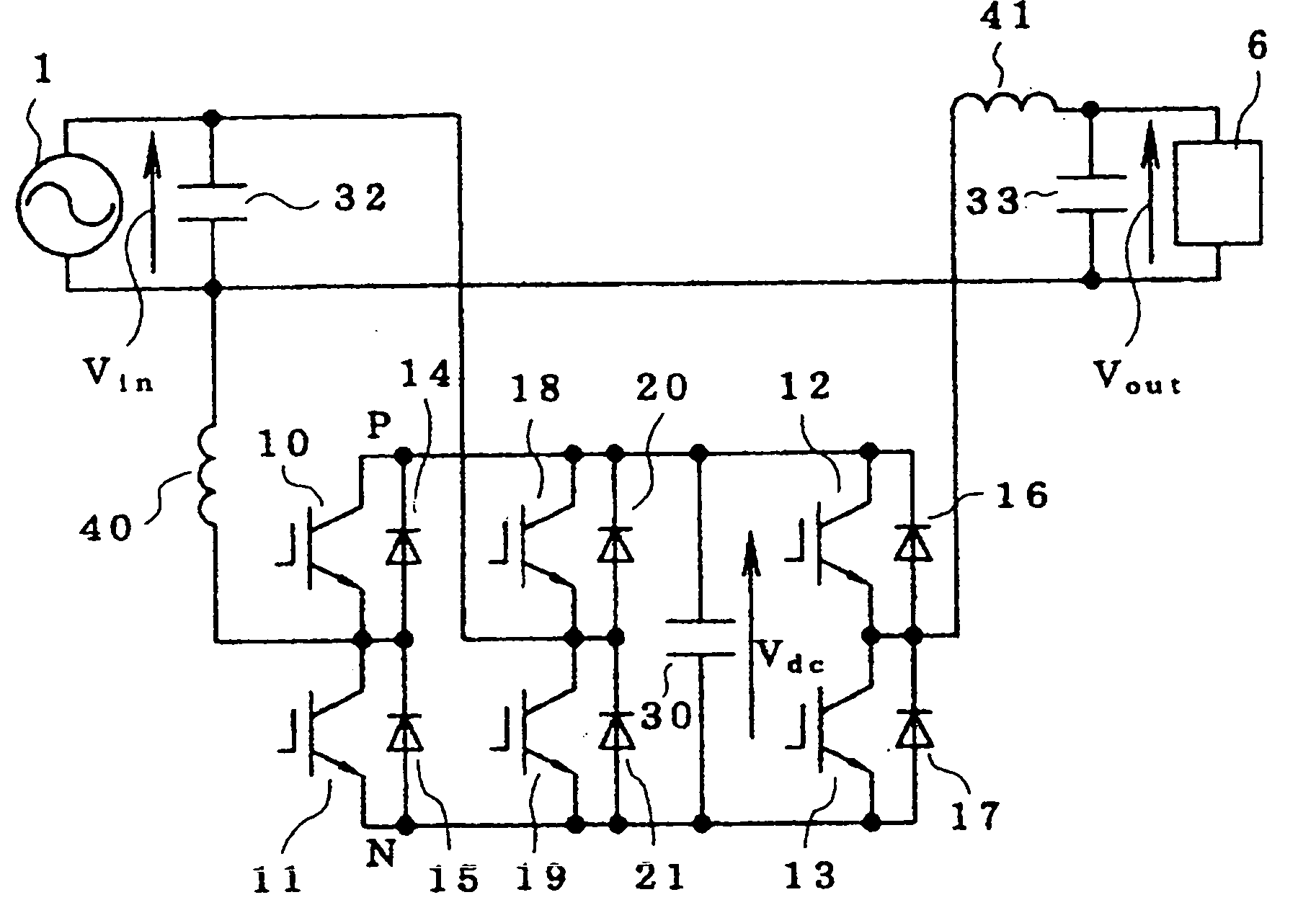
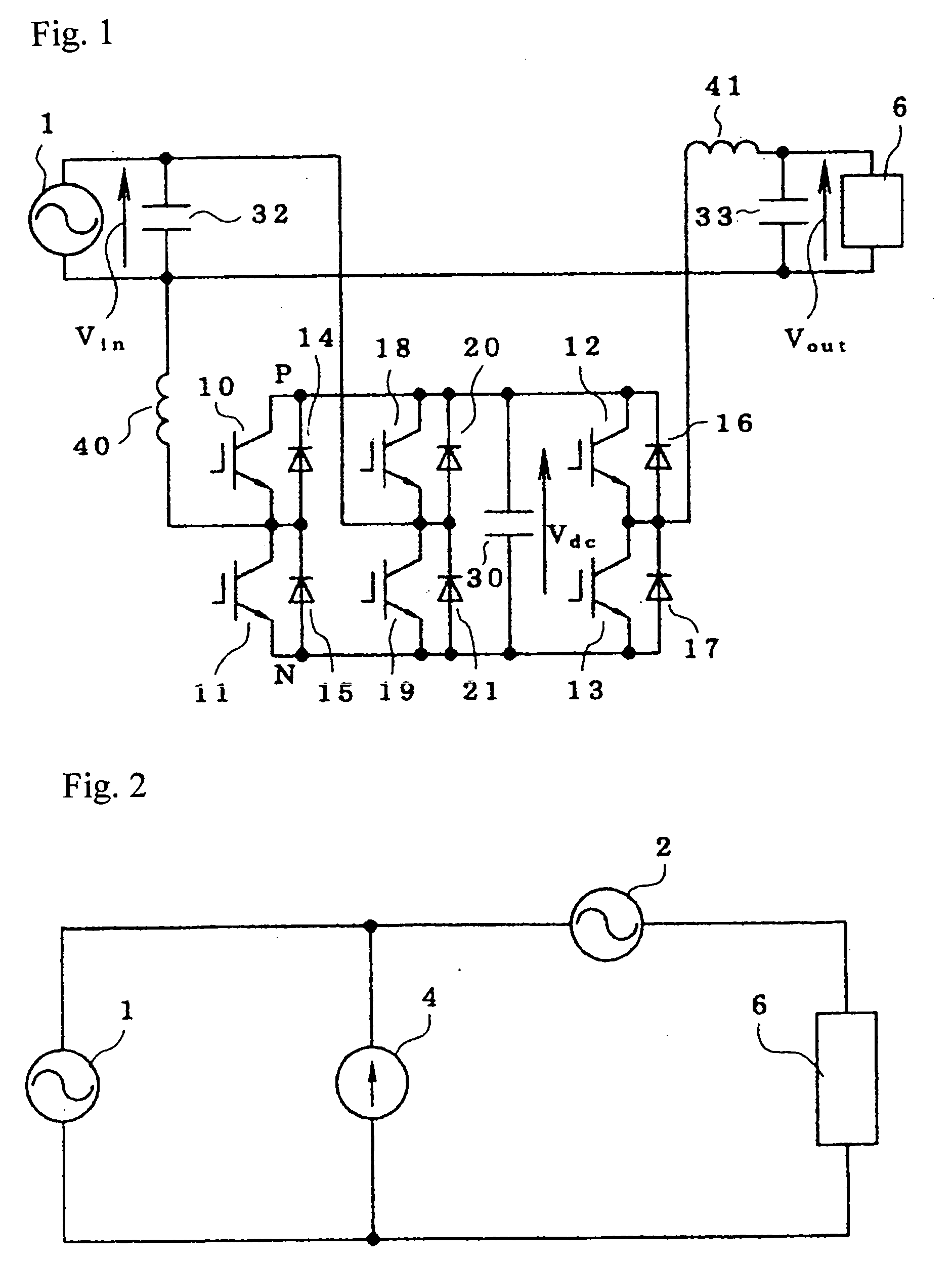
[0010] The second and third switching element series circuit can form a series converter, which can compensate a change in voltage of the AC power source to supply a constant voltage to the load. The first and second switching element series circuits can form a parallel converter, which can compensates a change in voltage of the first capacitor due to the compensating operation of the series converter by a charging and discharging operation between the AC power source and the first capacitor.

Problems solved by technology

In this configuration, the loss generated by each of the converters becomes large.
Thus, the problem of reducing conversion efficiency increases the running cost.
Thus, the applied elements require a high breakdown voltage.
This further increases the cost.

Method used


Image

  • Electric power converting device
  • Electric power converting device
  • Electric power converting device

Examples


fourth embodiment

[0051] Referring to FIG. 6, the fourth embodiment is identical to the embodiment of FIG. 5, but further includes separate charging and discharging units 62, 63 in place of the common charging and discharging unit 61. The charging unit 62 is connected across the AC power source 1 while the discharging unit 63 is connected between the points P and N, and the energy storing element 60 is connected in parallel to the charging unit 62 and the discharging unit 63. The charging unit 62, discharging unit 63, and the energy storing element 60 also can be added to the embodiment of FIG. 1.

[0052] In operation of the fourth embodiment, the energy is kept charged in the energy storing element 60 by the charging unit 62 under a normal condition of the AC power source 1, while under an abnormal condition of the AC power source 1, for example, at power failure, the energy stored in the energy storing element 60 is supplied to the capacitor 30 via the discharging unit 63. With the capacitor 30 taken...

sixth embodiment

[0057] Referring to FIG. 8, the sixth embodiment is substantially similar to the embodiment of FIG. 1, but it further includes a voltage distinguishing circuit, a changeover switch 90, and another capacitor 31 connected with the capacitor 30. In this embodiment, a series circuit of the first capacitor (electrolytic capacitor) 30 and a fourth capacitor (electrolytic capacitor) 31 (referred to as a “capacitor series circuit”) are connected in parallel to one another. The other end of the AC power source 1 that is not directly connected to the load 6 is connected to a common terminal 91 of the changeover switch 90, which has first and second switching contacts 92, 93, the first switching contact 93 is connected to a series connection point of the third and fourth semiconductor switching elements 18, 19, and the second switching contact 92 is connected to a series connection point of the capacitors 30. To the AC power source 1, a voltage distinguishing circuit 70 for distinguishing whet...


PUM


Abstract

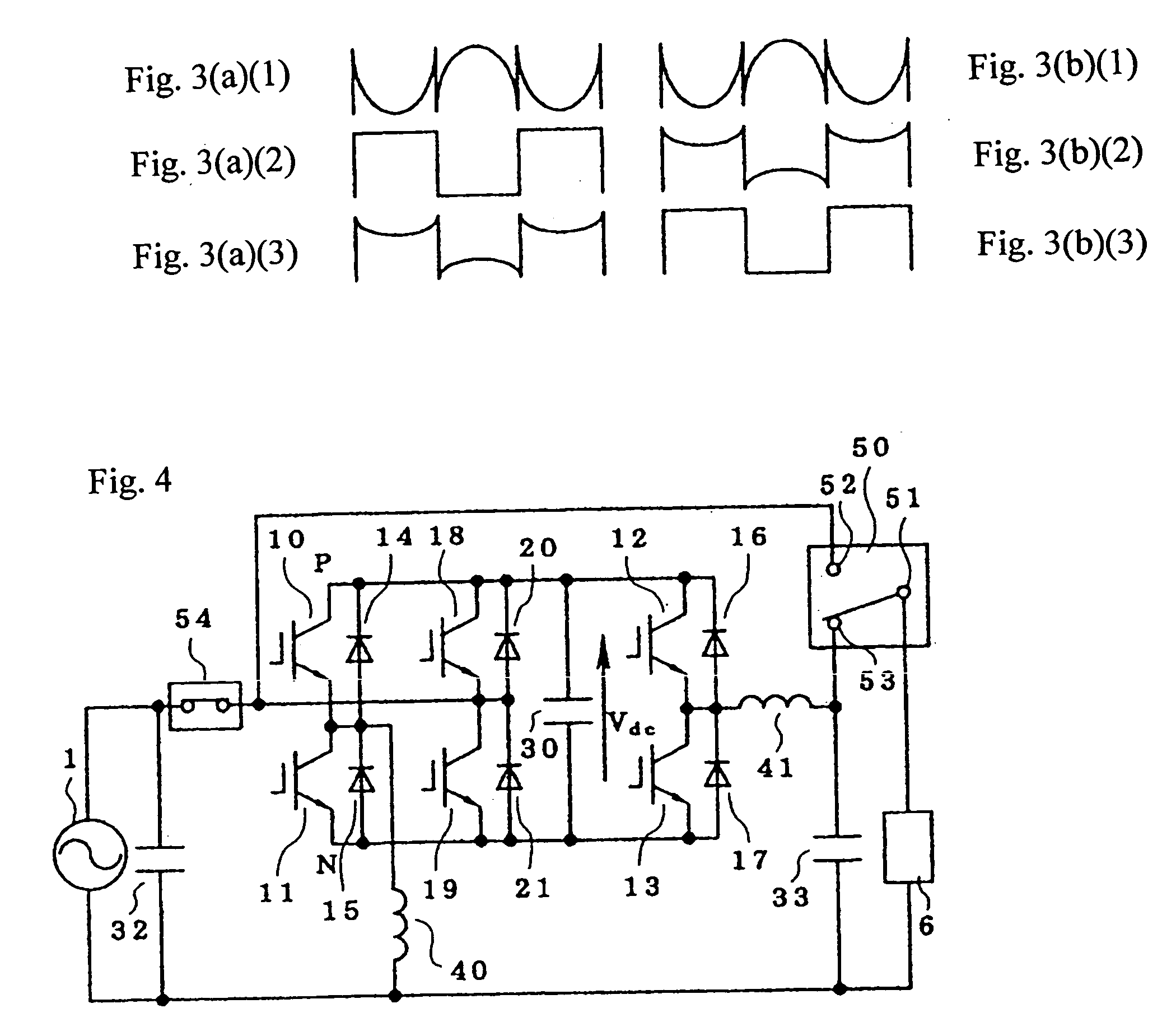
An electric power converting device can supply a constant voltage to a load while suppressing voltage variation in the AC power source, to reduce breakdown voltages of semiconductor switching elements. the device includes first to third switching element series circuits and at least a first capacitor connected in parallel. One end of the AC power source and one end of the load are connected to each other. Second and third capacitors are connected in parallel to the AC power source side and the load side, respectively. The one end of the power source is connected to a series connection point of the first switching element series circuit through a reactor, the other end of the power source is connected to a series connection point of the second switching element series circuit, and the other end of the load is connected to a series connection point of the third switching element series circuit through another reactor. Change in the power source voltage is compensated by a series converter, which is formed byes the second and third switching element series circuits, and change in voltage of the capacitor due to the compensating operation is compensated by charging and discharging operation by a parallel converter formed by the first and second switching element series circuits.

Description

BACKGROUND [0001]FIG. 10 illustrates a circuit of a conventional electric power converting device for once converting alternating-current (AC) electric power to direct-current (DC) electric power and further converting it to AC electric power. In FIG. 10, to one end of an AC power source 1, a series circuit of semiconductor switching elements 10, 11 is connected through a reactor 40. To the semiconductor switching elements 10, 11, diodes 14, 15 are connected in inverse parallel, respectively. The semiconductor switching elements 10, 11 undergoes PWM (Pulse Width Modulation) so that they operate as a rectifier circuit together with the diodes 14, 15 to control the converting operation while storing energy in capacitors 30, 31 connected in series so that the voltage of the capacitors 30, 31 becomes a specified DC voltage. [0002] Moreover, to the series circuit of the capacitors 30, 31, a series circuit of semiconductor switching elements 12, 13 are connected in parallel. To the semico...

Claims


Application Information

Patent Timeline
Patent Type & Authority Applications(United States)
IPC IPC(8): H02J9/06H02M1/10H02M5/458H02M7/48H02M7/5387
CPCH02J9/062H02M1/10Y02B70/1491H02M2001/0048H02M5/4585Y02B70/10H02M1/0048
Inventor OKUMA, YASUHIRO
Owner FUJI ELECTRIC CO LTD
Why Eureka
Try Eureka