
Signal repeater and switching device, method of detecting connecting relation between signal repeater and switching device and communication system

a technology of switching device and signal repeater, which is applied in the field of detecting connection relation between signal repeater and switching device, and communication system, can solve problems such as erroneous registration, possible network faults, and network topology can be erroneously registered, so as to prevent meaningless switching and prevent erroneous registration

Inactive Publication Date: 2005-01-06
NEC CORP
View PDF10 Cites 23 Cited by
  • Summary
  • Abstract
  • Description
  • Claims
  • Application Information

AI Technical Summary

Benefits of technology

The present invention provides a method and system for detecting the connection between a signal repeater and a switching device in a communication system. This helps to prevent errors in the registration of the topology of the system and ensures that meaningless switching does not occur even in situations where no main signal is flowing. The method involves adding an identifier to a signal in the repeater and transmitting it to the switching device, setting the switching device's ports into a loop back state, and detecting the identifier in the repeater. This allows for the confirmation of the connection between the repeater's ports and the ports of the switching device. The system includes a switching device with bidirectional ports, signal repeaters with input and output ports, and a controller for controlling the switching device and signal repeaters. The method and system can improve the reliability and accuracy of the connection detection process and prevent errors in the system.

Problems solved by technology

When connections are visually confirmed to register the connectivity and network topology in the network management system, human errors, if any, would result in erroneous registration and possible network faults.
In particularly, when a network is re-started immediately after installation or replacement of a certain device, or due to a fault, the connecting relation must be registered again in the network management system, in which case the network topology can be erroneously registered due to a human error as mentioned above.

Method used


Image

  • Signal repeater and switching device, method of detecting connecting relation between signal repeater and switching device and communication system
  • Signal repeater and switching device, method of detecting connecting relation between signal repeater and switching device and communication system
  • Signal repeater and switching device, method of detecting connecting relation between signal repeater and switching device and communication system

Examples


first embodiment

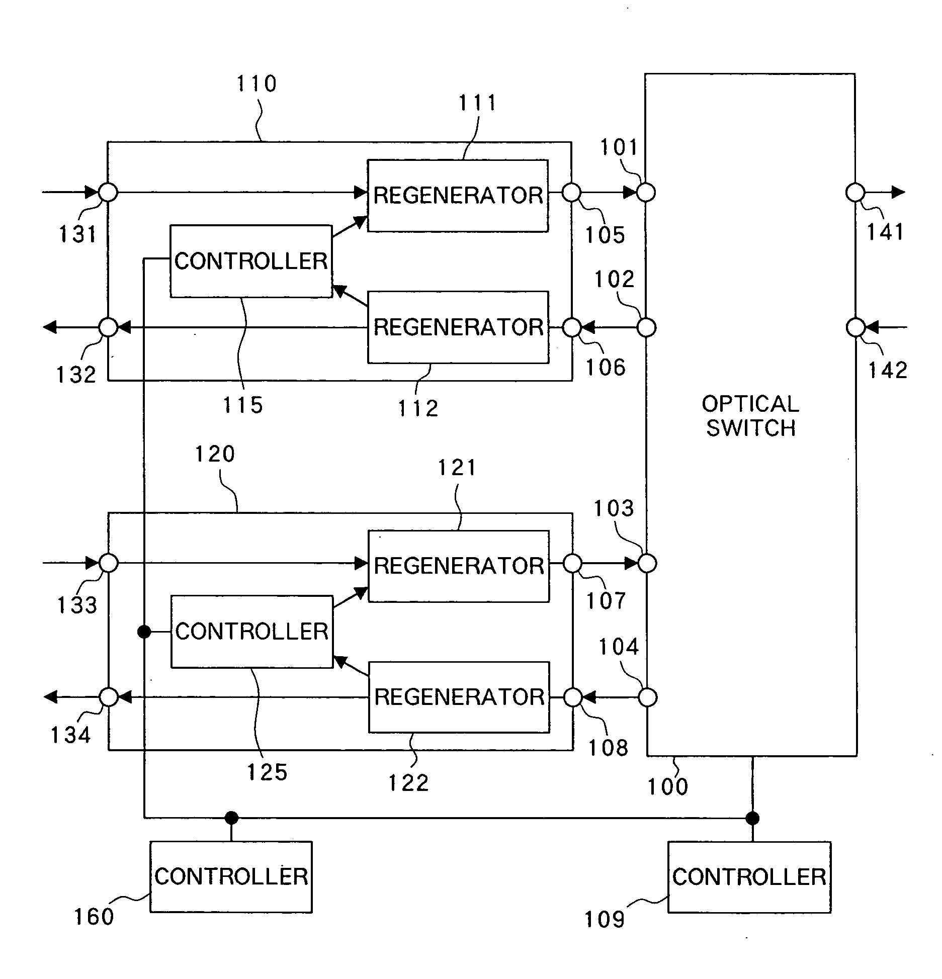
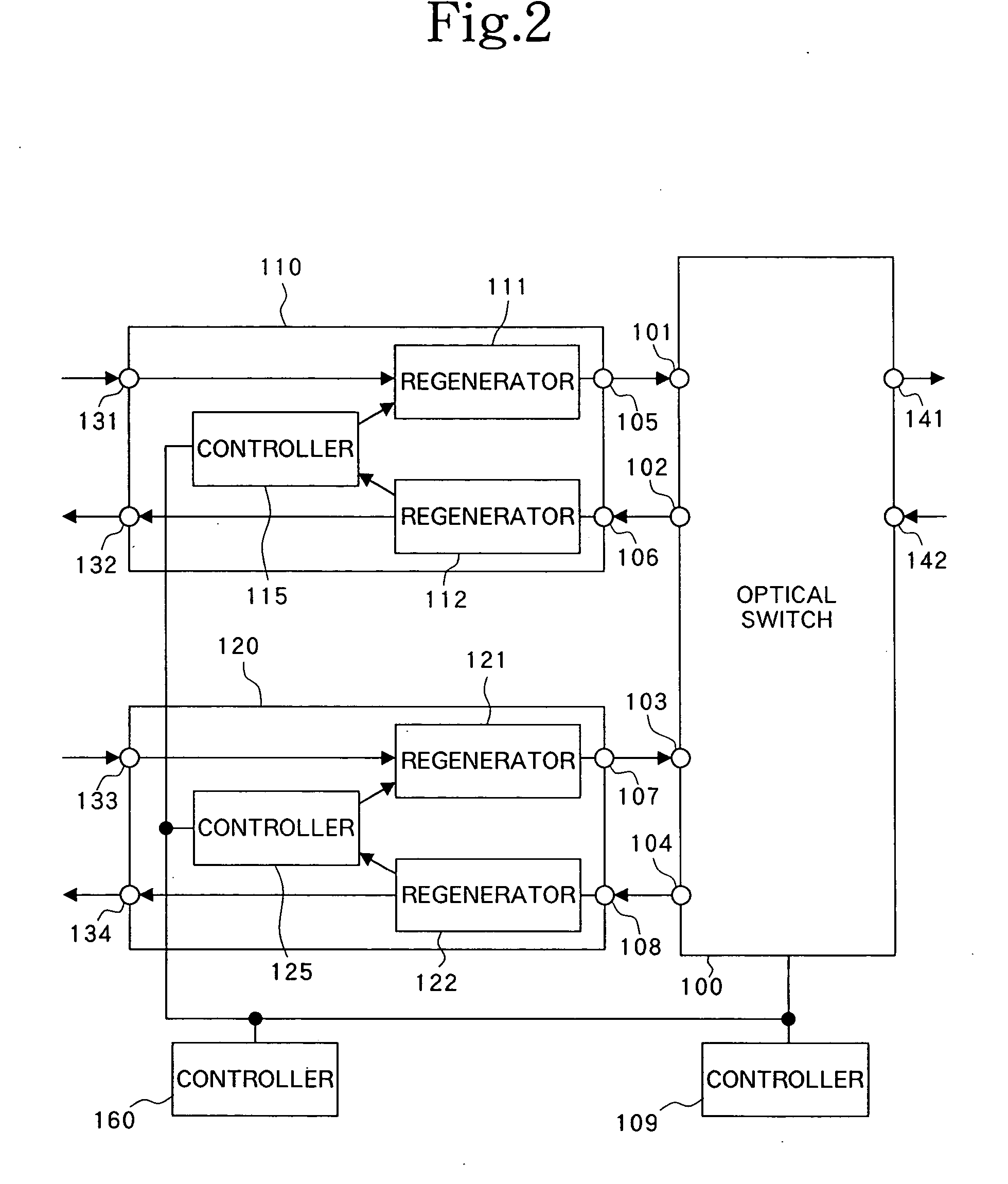
[0040] Referring first to FIGS. 2 to 5, a first embodiment will be described.

[0041] In FIG. 2, ports 101-108, 131-134, 141, 142; regenerators 111, 112, 121, 122; controllers 115, 125; bidirectional optical signal repeaters 110, 120; optical switch 100, and controller 109 are each designed to operate in a similar manner to ports 1101-1108, 1131-1134, 1141, 1142; regenerators 1111, 1112, 1122; controllers 1115, 1125; bidirectional optical signal repeaters 1110, 1120; optical switch 1100; and controller 1109, respectively, shown in FIG. 1. In this embodiment, controller 160 is provided in addition to the foregoing components for connection with controllers 115, 125 of respective bidirectional optical signal repeaters 110, 120 as well as for connection with controller 109.

[0042] Described first will be basic operations for checking connecting relations of bidirectional optical signal repeaters 110, 120 with respective ports of optical switch 100 in this embodiment.

[0043] For checking ...

third embodiment

[0076] Next, the present invention will be described with reference to the flow chart of FIG. 7 which illustrates a routine according to this embodiment.

[0077]FIG. 7 is identical in configuration to FIG. 2, only except for the connecting state of optical switch 100. Regenerators 101, 112 are 3R regenerative repeaters of SONET, where a B1 byte contains the result of parity operation in the transmission format, permitting odd-numbered bit errors, if any, to be detected. A bit error ratio can be calculated by detecting such bit errors over a certain period (see Bellcore document cited above in Description of Related Art). Consequently, the SONET regenerator has a means for adding information for evaluating the transmission quality after reception, and a means for calculating the transmission quality after reception while utilizing the information.

[0078] Assume now that management is desired on an optical link between port 105 and port 101 and an optical link between port 102 and port ...

fourth embodiment

[0080] Next, the present invention will be described with reference to FIGS. 8 and 10.

[0081]FIG. 8 is a flow chart illustrating a routine according to the fourth embodiment of the present invention. The flow chart of the fourth embodiment is identical to the flow chart of FIG. 5 illustrating the routine according to the first embodiment except for additional steps 312 and 313 as can be seen in FIG. 8.

[0082] Upon confirming at step 307 that an identifier added to a transmitted signal by a bidirectional signal repeater is different from an identifier extracted from a received signal (Yes at step 307), controller 160 checks identifiers received by other bidirectional signal repeaters to attempt to find reception of a signal which has the same identifier as an identifier added by a bidirectional signal repeater “m” for which a connecting relation is checked (step 312).

[0083] When it is confirmed at step 312 that another bidirectional signal repeater has received a signal having the sa...


PUM


Abstract

The present invention is intended to find a connecting state of a bidirectional signal repeater with an optical switch to prevent an erroneous registration of the topology. The present invention also has an object to confirm the normality of a link between the optical switch and bidirectional signal repeater even when no main signal is flowing by directing a signal from the bidirectional signal repeater to the optical switch. An identifier is added to the signal. One bidirectional port pair of the optical switch is set into a loop back configuration, without setting the remaining bidirectional port pairs into the loop back configuration. A controller checks whether or not a signal received by a regenerator is the same as a signal transmitted from a different regenerator. The normality of the link between the bidirectional signal repeater and optical switch is confirmed to evaluate the quality of a signal which returns from the bidirectional port pair which is in the loop back state.

Description

BACKGROUND OF THE INVENTION [0001] 1. Field of the Invention [0002] The present invention relates to a method of detecting a connecting relation between a signal repeater and a switching device, and a communication system suitable for implementation of the detecting method. [0003] 2. Description of the Related Art [0004] Networks have been configured using a method of switching time slots which are time-division-multiplexed on an optical signal, where an increased switching unit of a communication network associated with an increase in communication traffic results in requirements for a function of switching the unit of optical signals. This function is implemented using an optical cross-connect system (OXC) which is based on an optical switch. [0005]FIG. 1 is a block diagram illustrating the configuration of an exemplary prior art optical cross-connect system. Here, a device which has a function of receiving a certain signal and delivering this signal after it has undergone process...

Claims


Application Information

Patent Timeline
Patent Type & Authority Applications(United States)
IPC IPC(8): H04Q11/00H04L12/70
CPCH04Q11/0005H04Q2011/002H04Q2011/0083H04Q2011/0049H04Q2011/0039
Inventor SHIRAGAKI, TATSUYA
Owner NEC CORP
Learn More