
Per-flow rate control for an asynchronous metro packet transport ring

a technology of per-flow rate control and asynchronous data packets, applied in the direction of data switching networks, digital transmission, electrical equipment, etc., can solve the problems of ineffective entrance or exit ramps, high unreliable and unpredictable process, and limited internet activities, so as to achieve the effect of curing the processing overhead associated

Inactive Publication Date: 2005-01-06
ARRIS ENTERPRISES LLC
View PDF6 Cites 17 Cited by
  • Summary
  • Abstract
  • Description
  • Claims
  • Application Information

AI Technical Summary

Benefits of technology

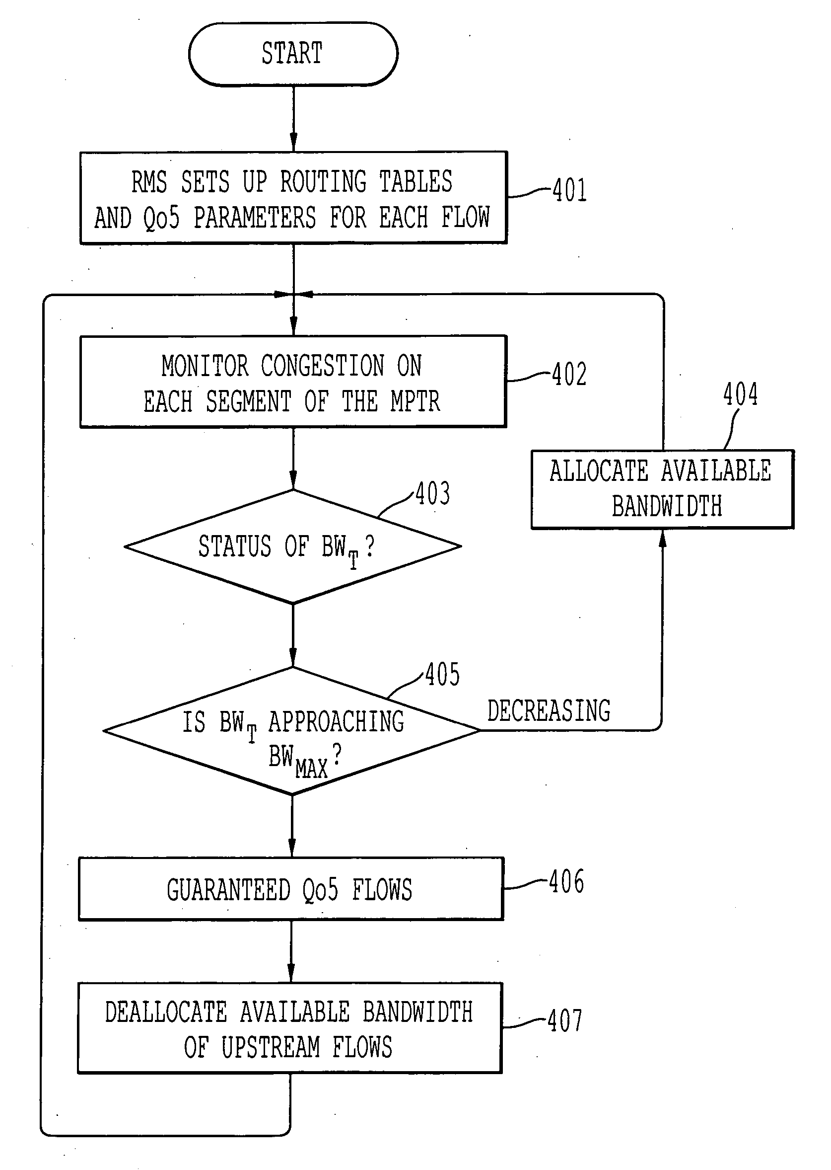
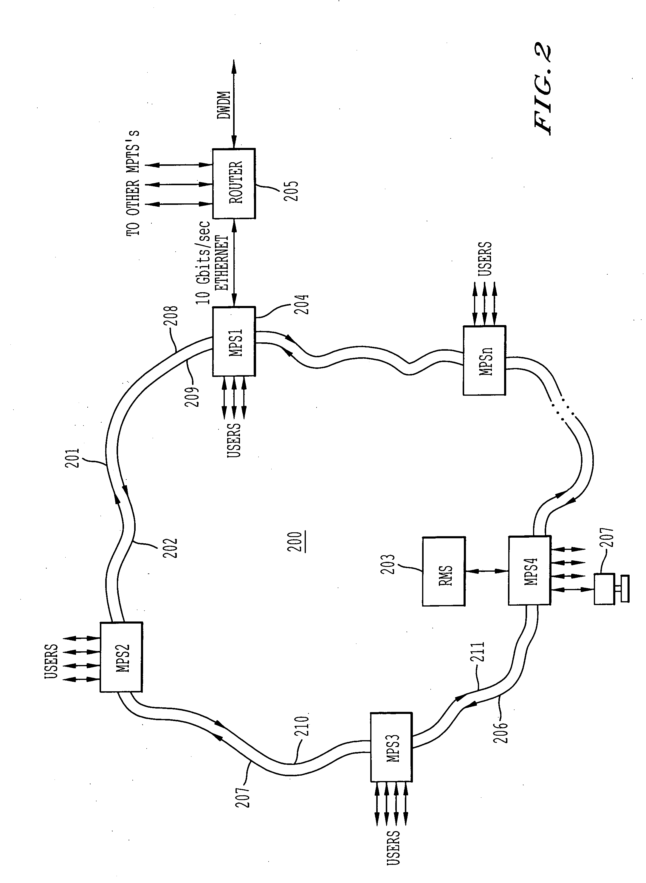
The present invention is about a metropolitan packet transport ring (MPTR) that allows for the efficient transport of packetized data in an asynchronous environment. The MPTR eliminates the need for expensive synchronization circuits and processing overhead associated with traditional TDM mechanisms. It includes a fiber optic loop and a number of metropolitan packet switches (MPS's) that allow computing and networking devices to access the fiber optic loop. The MPS monitors the traffic flowing in its particular segment of the network and regulates the data rates of each flow to provide quality of service (QoS) to certain subscribers. The MPS can also allocate unused bandwidth to other flows based on a pre-specified weighting scheme. The RMS is used for initial bandwidth allocation and can adjust data rates on a per-flow basis. The invention guarantees QoS in an asynchronous packetized data environment on a per-flow basis and ensures efficient use of bandwidth with minimal wasted bandwidth.

Problems solved by technology

In the past, activities over the Internet were limited due to the relatively slow connection speeds of dial-up modems over conventional telephone lines.
However, there is a problem with distributing the bandwidth of this new fiber optic network to end users.
Essentially, this next-generation information superhighway has no real, effective entrance or exit ramps.
Although this process is standard and well-accepted, it suffers from several drawbacks.
Due to traffic congestion, network overhead, routing conditions, and other uncontrollable external factors, this process is highly unreliable and unpredictable.
As such, the reliability of traditional LAN switches and routers is limited.
Consequently, it is virtually impossible to provide any kind of quality of service (QoS) using traditional LAN switches and routers.
For real-time applications such as video on demand, HDTV, voice communications, etc., dropped packets or late-arriving packets can seriously disrupt or even destroy performance.
For example, a e-commerce or business web site may lose critical revenue from lost sales due to customers not being able to access their site during peak hours.
However, these mechanisms are all extremely expensive to implement.
Although TDM enables QoS, it is costly to implement because both the transmitter and receiver must be synchronized at all times. The circuits and overhead associated with maintaining this precise synchronization is costly.
Furthermore, TDM based networking technologies are highly inefficient in that if a user does not transmit data within his dedicated time slot, that time slot goes empty and is wasted.
In other words, TDM employs a use-it-or-lose-it approach whereby unused bandwidth is totally wasted; unused bandwidth cannot be reallocated to a different user.
Although the Internet backbone is being substantially overhauled to substantially increase its bandwidth, there is no mechanism in place today for distributing this bandwidth to end users that is cost-efficient, effective and yet which also has the ability of providing rate control on a per-flow basis.

Method used


Image

  • Per-flow rate control for an asynchronous metro packet transport ring
  • Per-flow rate control for an asynchronous metro packet transport ring
  • Per-flow rate control for an asynchronous metro packet transport ring

Examples


Embodiment Construction

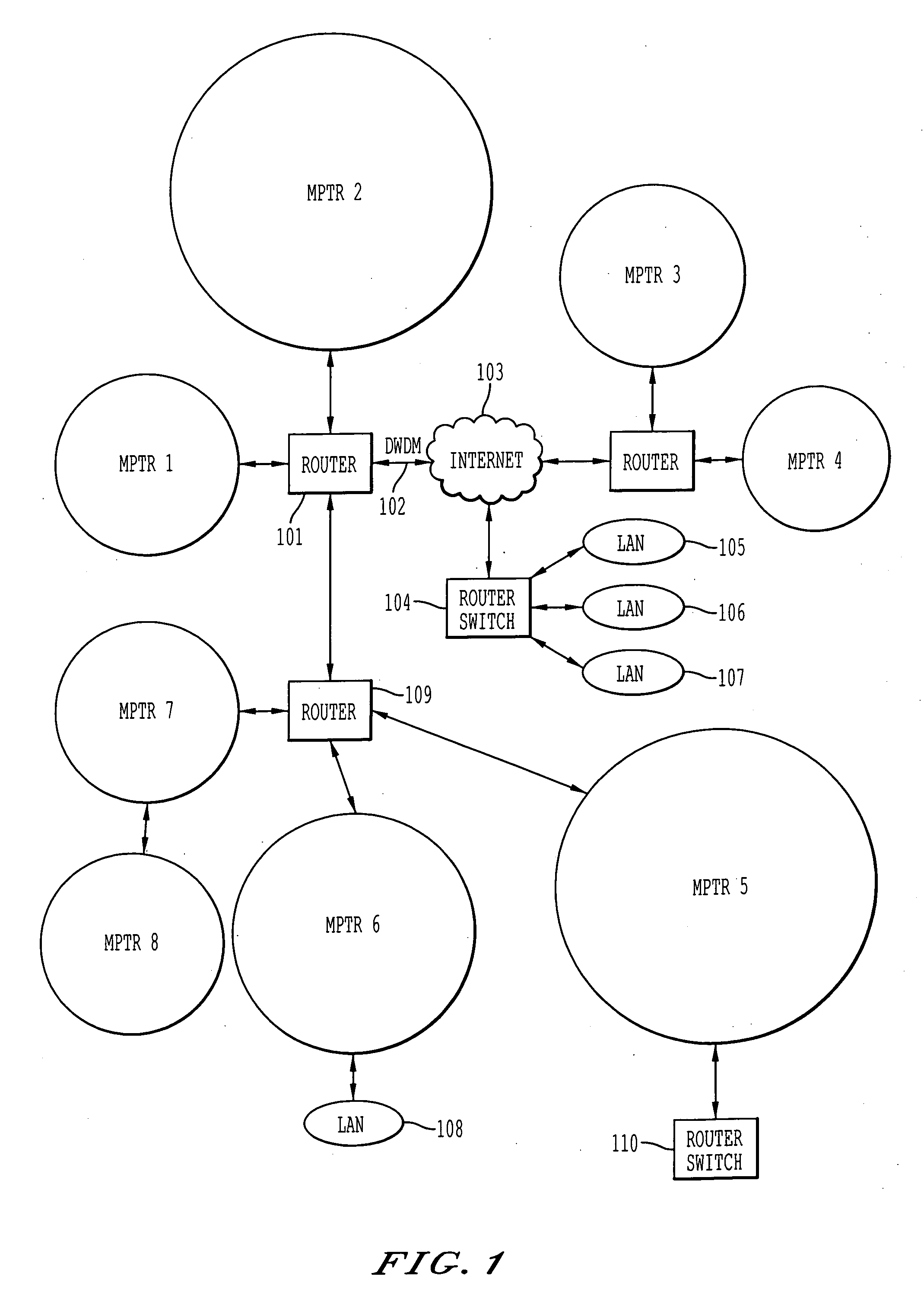
[0021] An asynchronous metro packet transport ring network is described. In the following description, for purposes of explanation, numerous specific details are set forth in order to provide a thorough understanding of the present invention. It will be obvious, however, to one skilled in the art that the present invention may be practiced without these specific details. In other instances, well-known structures and devices are shown in block diagram form in order to avoid obscuring the present invention.

[0022]FIG. 1 shows the overall architecture of the asynchronous metro packet transport ring network according to the currently preferred embodiment of the present invention. A metropolitan packet transport ring (MPTR) consists of a loop which is laid to transmit data packets in a metropolitan area network (MAN). A MAN is a backbone network which spans a geographical metropolitan area. Typically, telephone companies, cable companies, and other telecommunications providers supply MAN...


PUM


Abstract

An asynchronous metropolitan packet transport ring having per-flow QoS. Asynchronous packetized data flow in one direction through a fiber optic loop. A number of Metropolitan Packet Switches (MPS) are coupled to the fiber optic loop. An MPS allows packetized data from an upstream MPS to flow to a downstream MPS over a segment of the fiber optic loop. The MPS also puts packetized data onto and pulls packetized data off of the fiber optic loop. Thereby, flows can access the fiber optic loop via the MPS's. The MPS's also regulate the data rates on a per-flow basis according to setup information supplied by a Ring Management System (RMS). If one segment of the fiber loop becomes overly congested, the MPS guarantees quality of service for those flows by deallocating available bandwidth from flows upstream to the point of congestion. Utilization of packet transport ring capacity is optimized by allocating any bandwidth that becomes available to active flows according to a pre-specified weighting scheme.

Description

FIELD OF THE INVENTION [0001] The present invention relates to an apparatus and method for the per-flow rate control of asynchronous data packets flowing in a metro packet transport ring. BACKGROUND OF THE INVENTION [0002] The Internet is a general purpose, public computer network which allows millions of computers all over the world, hooked into the Internet, to communicate and exchange digital data with other computers also coupled to the Internet. Once a computer is coupled to the Internet, a wide variety of options become available. Some of the myriad functions possible over the Internet include sending and receiving electronic mail (e-mail) messages, browsing different web sites, downloading and / or uploading files, etc. In the past, activities over the Internet were limited due to the relatively slow connection speeds of dial-up modems over conventional telephone lines. [0003] However, as new technologies emerge, the speed at which one can connect onto the Internet is ever incr...

Claims


Application Information

Patent Timeline
Patent Type & Authority Applications(United States)
IPC IPC(8): H04L12/433H04L12/56
CPCH04L12/433H04L47/10H04L47/11H04L47/20H04L2012/5651H04L47/762H04L2012/5605H04L2012/5612H04L47/2441
Inventor VIJEH, NADERMEKKITTIKUL, ADISAK
Owner ARRIS ENTERPRISES LLC
Learn More