Optical transmission device

a transmission device and optical fiber technology, applied in the field of optical transmission devices, can solve the problems of complex control, high cost of equipment for realizing dwdm, and large equipment for realizing dwdm, and achieve the effect of improving optical transmission quality and efficient suppression of loss levels of optical fiber transmission

Inactive Publication Date: 2005-01-06
FUJITSU LTD
View PDF13 Cites 13 Cited by
  • Summary
  • Abstract
  • Description
  • Claims
  • Application Information

AI Technical Summary

Benefits of technology

[0020] The present invention is made in view of the above problems, and the object of the present invention is to provide an optical transmission device which efficiently suppresses variations in loss levels in optical fiber transmission, and improves quality in optical transmission.
[0021] In order to accomplish the above object, an optical transmission device for performing transmission of an optical signal is provided. The optical transmission device comprises: a WDM port as a port for transmission and reception of a wavelength-multiplexed signal; and a wavelength multiplex / demultiplex unit which has a loss characteristic compensating for a wavelength-dependent loss characteristic of an optical transmission line, performs at least one of wavelength demultiplexing of a signal received through the WDM port and wavelength multiplexing for outputting a signal through the WDM port, and suppresses differences among different channels in loss caused by transmission of a wavelength-multiplexed signal so as to equalize loss levels in the different channels in the wavelength-multiplexed signal.

Problems solved by technology

However, since the wavelength range allocated to each wavelength channel is narrow, the control is complicated, elements constituting equipment for realizing DWDM are expensive.
In addition, since the equipment for realizing DWDM is massive, DWDM is mainly used in backbone networks.
However, since the wavelengths (channels) used in CWDM transmission are thinly dispersed over a wide wavelength range, the characteristics of optical transmission lines cause variations in loss among wavelength-multiplexed signals in different channels.
Therefore, the device size and cost increase, and the maintenance efficiency is low.

Method used


Image

  • Optical transmission device
  • Optical transmission device
  • Optical transmission device

Examples


Embodiment Construction

[0041] Embodiments of the present invention are explained below with reference to drawings.

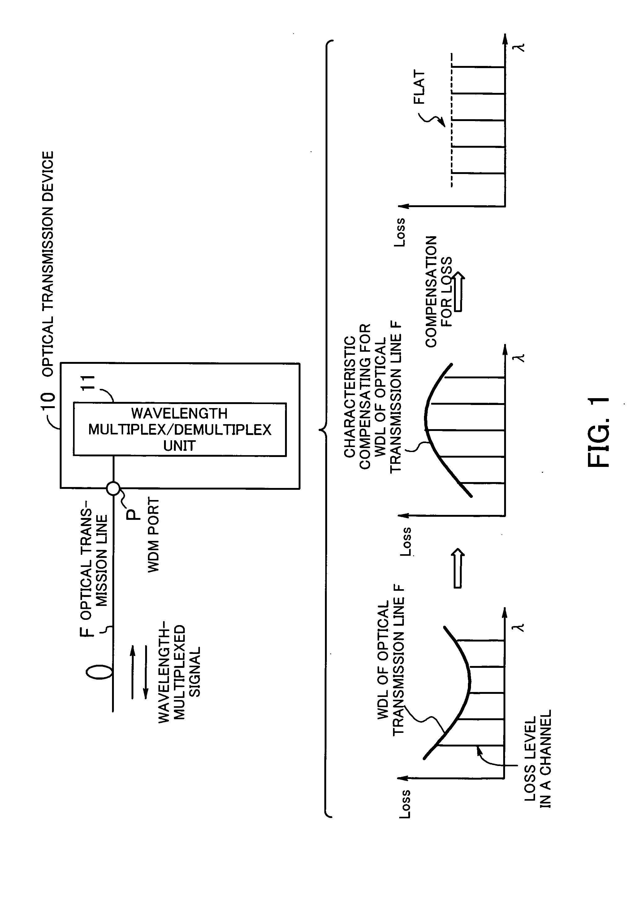
[0042]FIG. 1 is a diagram illustrating the principle of an optical transmission device according to the present invention. The optical transmission device 10 according to the present invention is used in a system for performing communication through a plurality of channels arranged in a wide wavelength range, and transmits WDM optical signals. In the following explanations, CWDM is taken as an example.

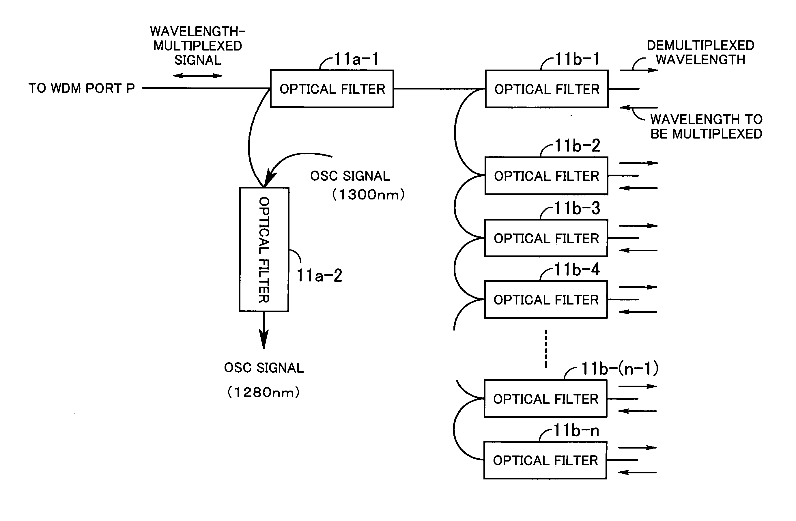
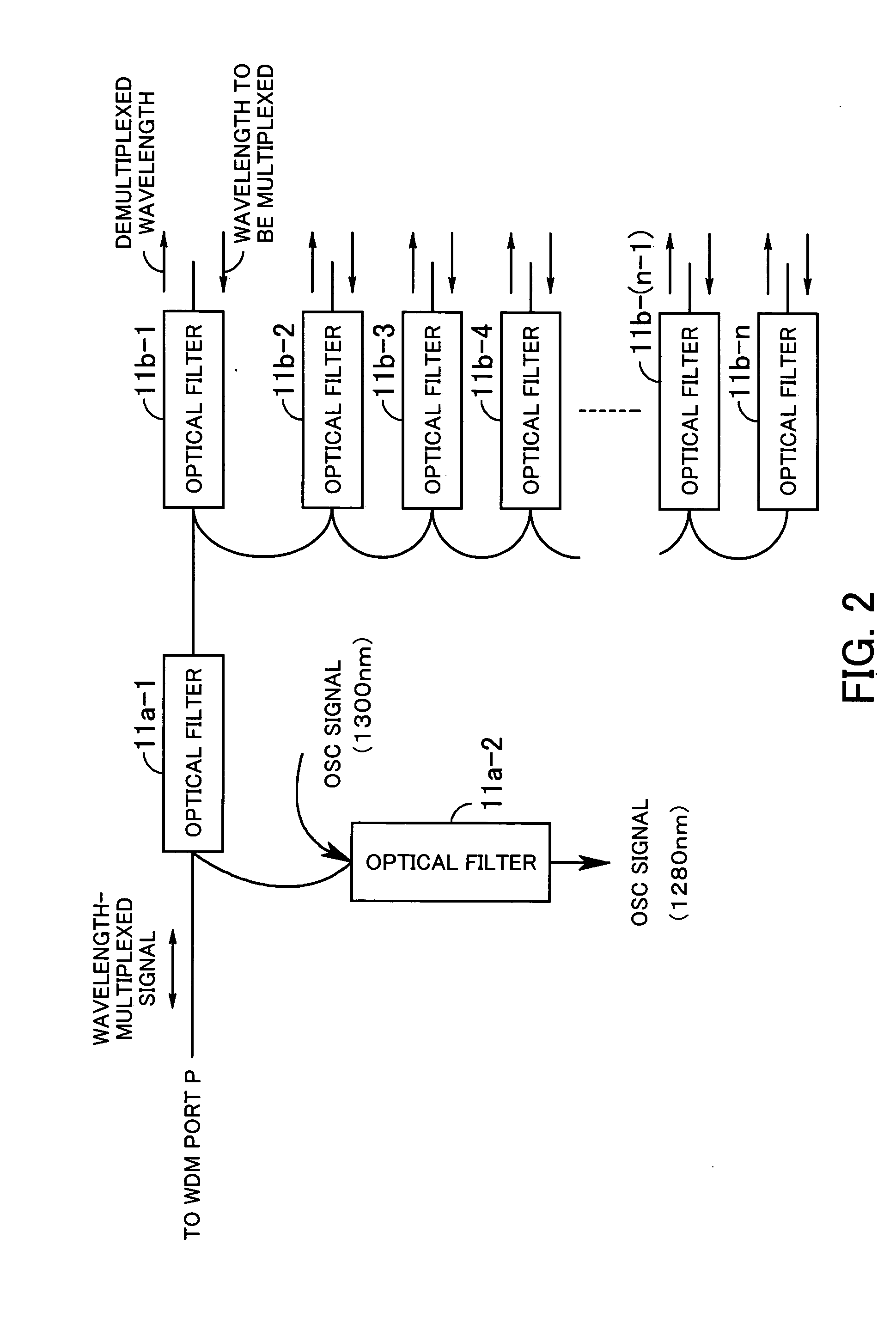
[0043] In the optical transmission device 10, a WDM port P is connected to an optical transmission line F, and functions as a port for transmission and reception of wavelength-multiplexed signals. The wavelength multiplex / demultiplex unit (wavelength multiplex / demultiplex coupler) 11 performs at least one of wavelength separation (demultiplexing) of signals received through the WDM port and wavelength multiplexing for outputting signals from the WDM port P. The wavelength multiplex / demultiplex ...


PUM


Abstract

An optical transmission device which efficiently suppresses variations among loss levels in optical fiber transmission, and improves quality of optical transmission. A WDM port is connected to an optical transmission line, and functions as a port for transmission and reception of a wavelength-multiplexed signal. A wavelength multiplex / demultiplex unit has optical filters which are daisy-chain connected, and realize a loss characteristic weighted at respective wavelengths in correspondence with a wavelength-dependent loss characteristic of the optical transmission line. Each of the optical filters has a function of a band-pass filter and an identical insertion loss. The wavelength multiplex / demultiplex unit performs wavelength demultiplexing of a signal received through the WDM port, or wavelength multiplexing of signals to be outputted through the WDM port, so as to suppress differences among different channels in loss caused by transmission of a wavelength-multiplexed signal, and equalize loss levels in the different channels.

Description

BACKGROUND OF THE INVENTION [0001] 1) Field of the Invention [0002] The present invention relates to an optical transmission device. In particular, the present invention relates to an optical transmission device which performs WDM (wavelength division multiplex) transmission of optical signals. [0003] 2) Description of the Related Art [0004] In the fields of optical communication networks, there are demands for sophistication of services and expansion of service areas, and WDM is beginning to be widely used as an optical transmission technique. WDM is a technique in which signals in a plurality of channels are concurrently transmitted through a single optical fiber by multiplexing light having different wavelengths. In addition, with the rapid increase in communication traffic, the numbers of wavelengths to be used are increasing, and a kind of WDM called DWDM (Dense WDM) has been developed. In DWDM, high-density wavelength multiplexing is performed. [0005] According to DWDM, up to ...

Claims


Application Information

Patent Timeline
Patent Type & Authority Applications(United States)
IPC IPC(8): H04J14/00H04B10/07H04B10/077H04B10/27H04B10/29H04J14/02
CPCH04B10/25073H04J14/0221H04J14/02
Inventor SAKAI, YUKIKOIMAI, KAZUTOTAKAHASHI, TSUKASAIKEDA, HIROTO
Owner FUJITSU LTD
Why Eureka
Try Eureka