Flexible vascular inducing implants

a vascular induction and implant technology, applied in the field of flexible vascular induction implants, can solve the problems of ischemic tissue infarction, permanent non-function, pain in the affected area, etc., and achieve the effects of increasing blood flow, high degree of flexibility, and maximizing blood exchang

Inactive Publication Date: 2005-01-06
GAMBALE RICHARD A +4
View PDF99 Cites 43 Cited by
  • Summary
  • Abstract
  • Description
  • Claims
  • Application Information

AI Technical Summary

Benefits of technology

[0016] Implant embodiments may further be prepared to initiate angiogenesis by having a thrombus of blood associated with them at the time of their implantation or inserted in the interior immediately following implantation. The thrombus of blood may be taken from the patient prior to the implant procedure and is believed to help initiate the tissue's healing response which leads to angiogenesis.
[0027] It is another objective of the present invention to provide an implant delivery system that is safe and simple to use while minimizing trauma to the patient.

Problems solved by technology

Ischemia causes pain in the area of the affected tissue and, in the case of muscle tissue, can interrupt muscular function.
Left untreated, ischemic tissue can become infarcted and permanently non-functioning.
Muscle tissue affected by ischemia can cause pain to the individual affected.
Although others have reported varying degrees of success with various methods of piercing the myocardium to restore blood flow to the muscle, many have faced common problems such as closure of the created channels.
Reportedly, many of these methods still produced trauma and tearing of the tissue that ultimately led to closure of the channel.
Although there has been some published recognition of the desirability of performing transmyocardial revascularization (TMR) in a non-laser catheterization procedure, there does not appear to be evidence that such procedures have been put into practice.

Method used


Image

  • Flexible vascular inducing implants
  • Flexible vascular inducing implants
  • Flexible vascular inducing implants

Examples


Embodiment Construction

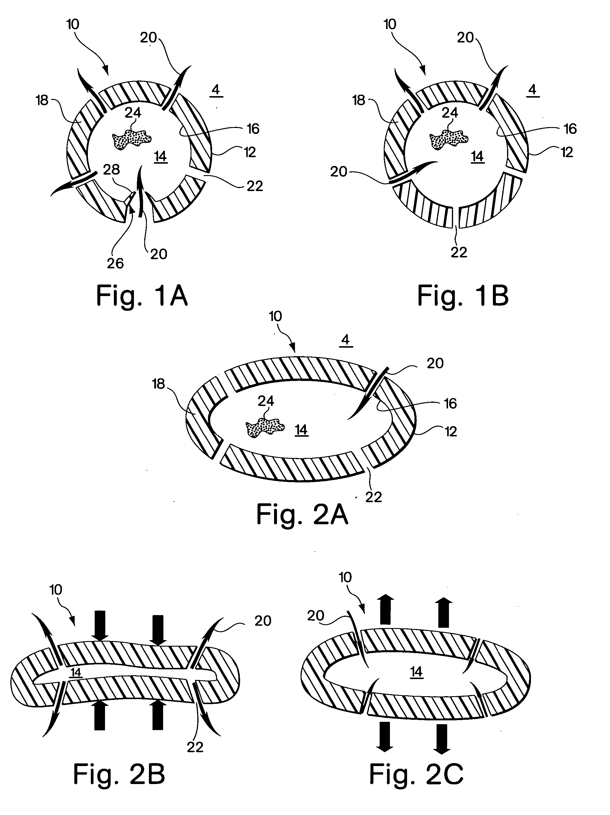
[0055]FIGS. 1A and 1B show one embodiment of the implant device comprising a capsule 10. The capsule embodiment has an exterior surface 12, a volume defining interior 14 with an inside surface 16. The wall 18 of the capsule may be somewhat flexible to permit flexure with the movement and compressive forces of the surrounding tissue 4 into which it is implanted. However, the wall should be fabricated to provide sufficient structural support to resist complete collapse of the capsule when it flexes.

[0056] Blood flow, represented by arrows 20, is intended to enter and exit the implant as part of the function of the device. As shown in FIG. 1B, blood 20 from the surrounding tissue 4 enters the interior 14 of the implant 10 through an opening 22. There may be several additional openings 22 to increase the amount of blood that can be exchanged through the device. Movement of the surrounding myocardial tissue 4 with the pumping of the heart flexes the capsule 10 and promotes blood interch...


PUM

PropertyMeasurementUnit
lengthaaaaaaaaaa
diameteraaaaaaaaaa
lengthaaaaaaaaaa

Abstract

Implants and associated delivery systems for promoting angiogenesis in ischemic tissue are provided. The implants may be delivered percutaneously, thoracically or surgically and are particularly well suited for implantation into the myocardium of the heart. The implants are configured to be flexible so that they compress and expand with corresponding movement of the surrounding tissue into which they are implanted. The flow of blood into the implant and pooling of the blood in and around the implant leads to thrombosis and fibrin growth, a healing process that leads to angiogenesis in the tissue surrounding the implant. Additionally, the implants may contain an angiogenic substance or a thrombus of blood, preloaded or injected after implantation to aid in initiating angiogenesis.

Description

RELATED APPLICATION [0001] This application is a divisional of application Ser. No. 09 / 164,163 filed Sep. 30, 1998.FIELD OF THE INVENTION [0002] This invention relates to methods and devices for inducing angiogenesis in ischemic tissue. BACKGROUND OF THE INVENTION [0003] Tissue becomes ischemic when it is deprived of adequate blood flow. Ischemia causes pain in the area of the affected tissue and, in the case of muscle tissue, can interrupt muscular function. Left untreated, ischemic tissue can become infarcted and permanently non-functioning. Ischemia can be caused by a blockage in the vascular system that prohibits oxygenated blood from reaching the affected tissue area. However, ischemic tissue can be revived to function normally despite the deprivation of oxygenated blood because ischemic tissue can remain in a hibernating state, preserving its viability for some time. Restoring blood flow to the ischemic region serves to revive the ischemic tissue. [0004] Although ischemia can ...

Claims


Application Information

Patent Timeline
Patent Type & Authority Applications(United States)
IPC IPC(8): A61B17/00A61F2/00A61F2/02A61F2/94A61K9/22A61L27/00A61M37/00
CPCA61F2/2493A61F2230/0091A61F2250/0067A61F2/94
Inventor GAMBALE, RICHARD A.FORCUCCI, STEPHEN J.WEISER, MICHAEL F.CHOH, RICHARD T.FORDE, SEAN
Owner GAMBALE RICHARD A
Why Eureka
Try Eureka