Annuloplasty rings and methods for repairing cardiac valves

a technology of annuloplasty and cardiac valve, which is applied in the field of annuloplasty rings and methods for repairing cardiac valves, can solve the problems that the valve cannot be brought to full proper functioning, and achieve the effects of preventing prolapse of leaflet or leaflet, eliminating regurgitation, and facilitating coaptation of leaflet(s)

Inactive Publication Date: 2005-01-06
FLEXCOR
View PDF17 Cites 243 Cited by
  • Summary
  • Abstract
  • Description
  • Claims
  • Application Information

AI Technical Summary

Benefits of technology

[0033] An object of the present invention is to simplify the mitral valve repair procedures and obviate the need to perform anything other than an annuloplasty procedure, i.e., implantation of the annuloplasty ring, to completely correct a defective cardiac valve regardless of the number and types of particular defects inflicting the valve. Another object of the invention is to employ a single device and a single procedure to completely correct valve dysfunction. In certain circumstances where the device might not completely eliminate the need for adjunctive procedures, the number and complexity of these procedures and the time and expertise necessary to perform them would be significantly reduced.
[0035] A feature of the present invention is the provision of an implantable device having an annuloplasty ring and a restraining or support structure or mechanism for restraining the abnormal motion of at least a portion of one or more of the valve leaflets. The annuloplasty ring functions to correct the shape and size of the annulus bringing the leaflets in proximity to permit coaptation. The restraint mechanism functions to ensure proper coaptation of the leaflets, regardless of the number, type and anatomical location of the valvular defects, without the need for procedures other than proper implantation of the ring in most cases. As a result, specific chordal or leaflet procedures may not need to be performed as their collective ill-effects can be resolved solely by implantation of the subject device. In some cases, the surgeon may choose to perform relatively straightforward ancillary procedures such as a limited posterior leaflet resection or mobilization while allowing the restraint mechanism to correct any new or residual prolapse.
[0036] The restraining structure consists of one or more restraining members extending inside the orifice of the ring. The restraining member or members may have a variety of different shapes and configurations including, but not limited to, chord-shaped or ribbon-shaped, rigid, semi-rigid or flexible, straight or bowed, elastic or inelastic or solid. They can attach to the ring or to another member, forming any pattern, creating a net-like or rigid structure which prevents prolapse of the leaflet or leaflets. By restraining the prolapsing segment or by providing a new intra-annular coaptation plane, the restraint system facilitates coaptation of the leaflets(s) thereby eliminating the regurgitation. Thus, the restraining structure of the device corrects Type II valve dysfunction (leaflet prolapse) without the need for the usual additional ancillary procedures to correct leaflet prolapse such as leaflet resection, transfer or artificial chordal attachment.

Problems solved by technology

As is known from the use of conventional annuloplasty rings, even a properly sized and implanted ring, while adequately correcting the shape and size of the valve's annulus to fully correct mitral regurgitation when leaflet motion is normal (Type I valve dysfunction), does not necessarily bring the valve to full proper functioning when leaflet prolapse (Type II valve dysfunction) or severe leaflet restriction (Type III valve dysfunction) is present.

Method used


Image

  • Annuloplasty rings and methods for repairing cardiac valves
  • Annuloplasty rings and methods for repairing cardiac valves
  • Annuloplasty rings and methods for repairing cardiac valves

Examples


Embodiment Construction

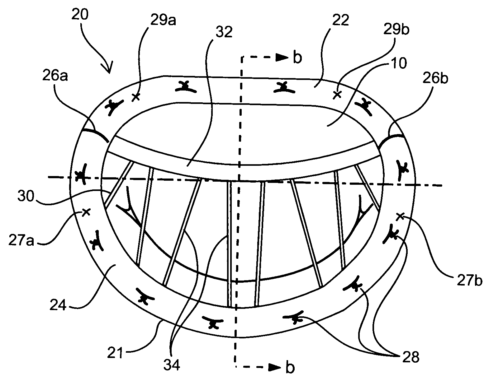
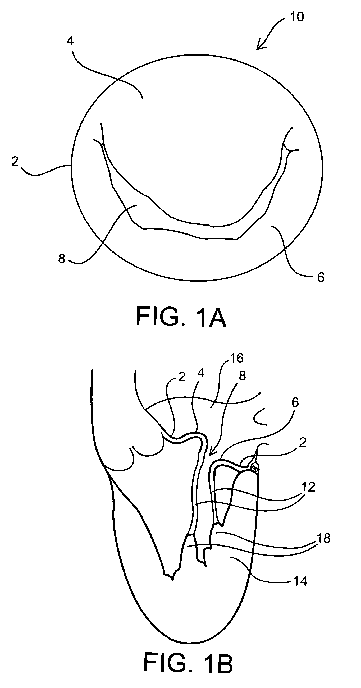
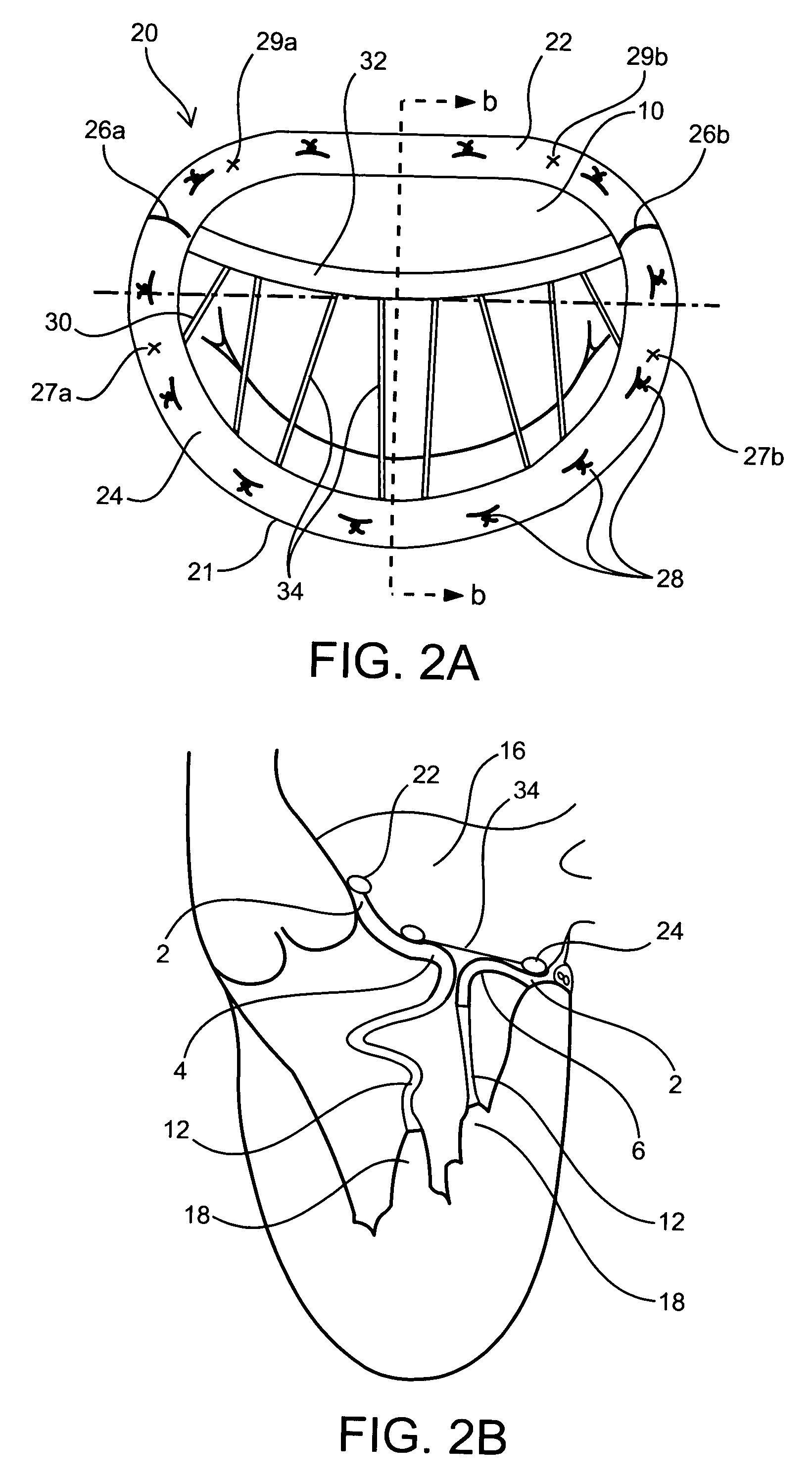
[0045] The present invention includes implantable prosthetic devices and methods of using the subject devices to repair cardiac valves. The prosthetic devices include annuloplasty rings which, when operatively employed, are sutured into the annulus of a defective or deformed valve, thereby correcting the defect or deformation and rendering the valve competent. Kits including at least one of the subject devices are also provided. The present invention is particularly suitable for repairing the mitral valve and, thus, is described in the context of mitral valve repair for purposes of example only. However, the present invention is also suitable for the repair of tricuspid valves and other valves.

[0046] Before the present invention is described, it is to be understood that this invention is not limited to particular embodiments described, as such may, of course, vary. It is also to be understood that the terminology used herein is for the purpose of describing particular embodiments o...


PUM


Abstract

Implantable devices and methods for the repair of a defective cardiac valve are provided. The implantable devices include an annuloplasty ring and a restraining or support structure or mechanism. The annuloplasty ring functions to reestablish the normal size and shape of the annulus bringing the leaflet in proximity to each other. The restraining structure functions to restrain the abnormal motion of at least a portion of the valve being repaired. The restraining structure may include at least one restraining member across the interior of the circumference of the ring in a configuration consisting of a primary member to which secondary members are attached or one where all members traverse the ring. Kits for using the devices and practicing the methods of the invention are also provided.

Description

FIELD OF THE INVENTION [0001] The invention relates to devices and methods for facilitating and simplifying the repair of cardiac valves. BACKGROUND OF THE INVENTION [0002] The human heart has four valves which control the direction of blood flow in the circulation. The aortic and mitral valves are part of the “left” heart and control the flow of oxygen-rich blood from the lungs to the body, while the pulmonic and tricuspid valves are part of the “right” heart and control the flow of oxygen-depleted blood from the body to the lungs. The aortic and pulmonic valves lie between a pumping chamber (ventricle) and major artery, preventing blood from leaking back into the ventricle after it has been ejected into the circulation. The mitral and tricuspid valves lie between a receiving chamber (atrium) and a ventricle preventing blood from leaking back into the atrium during ejection. [0003] Various disease processes can impair the proper functioning of one or more of these valves. These inc...

Claims


Application Information

Patent Timeline
Patent Type & Authority Applications(United States)
IPC IPC(8): A61F2/24
CPCA61F2/2454A61F2/2448
Inventor AKLOG, LISHAN
Owner FLEXCOR
Why Eureka
Try Eureka