Method and device for tank leakage diagnosis at elevated fuel degassing

Inactive Publication Date: 2005-01-13
ROBERT BOSCH GMBH
View PDF2 Cites 4 Cited by
  • Summary
  • Abstract
  • Description
  • Claims
  • Application Information

AI Technical Summary

Benefits of technology

[0010] Therefore, the exemplary method of the present invention is intended to avoid er

Problems solved by technology

A relatively high fuel degassing leads to erroneous measurements in tank leakage diagnosis.
In actual fact, however, because of the actually present high degassing, this would lead

Method used


Image

  • Method and device for tank leakage diagnosis at elevated fuel degassing
  • Method and device for tank leakage diagnosis at elevated fuel degassing
  • Method and device for tank leakage diagnosis at elevated fuel degassing

Examples


Embodiment Construction

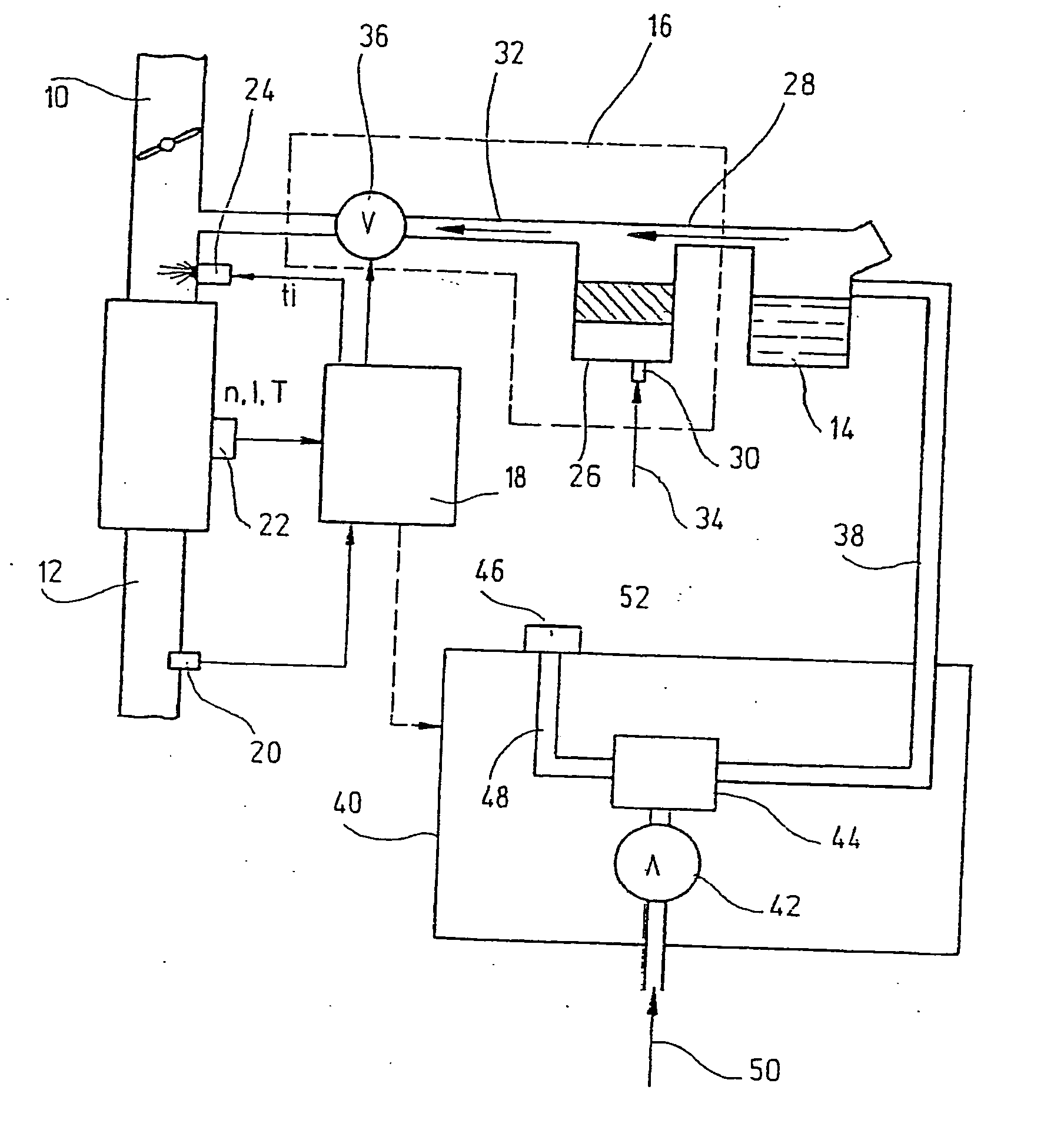
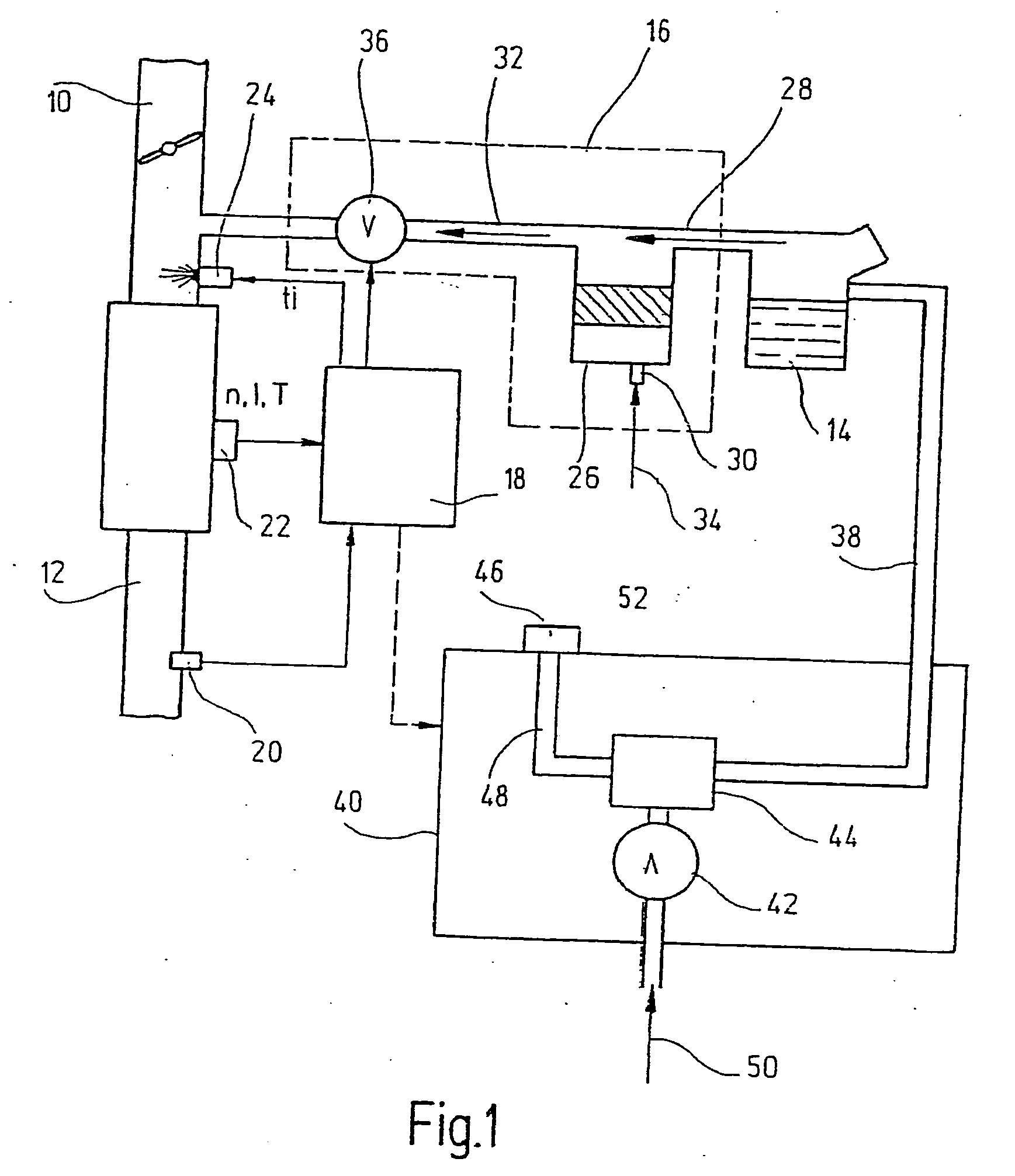
[0018]FIG. 1 shows an intake manifold 10 that may be provided in a (not shown) internal combustion engine (BKM) especially of a motor vehicle, as well as an exhaust gas tract 12. A fuel storage tank 14 is provided for fuel storage.

[0019] For the low-emission operation of the BKM, there are provided a tank venting device 16, a control unit 18, an exhaust gas sensor system 20, as well as a sensor system 22, which takes the place of a plurality of sensors ascertaining operating parameters of the BKM, such as a rotary speed sensors, flow meters for sensing the intake air quantity, temperature sensors, etc. The device shown also provides a fuel metering device 24, which, for instance, may be implemented as equipment for one or more injection valves.

[0020] Tank venting (ventilation) device 16 includes an active charcoal filter (AKF) 26, which communicates via corresponding lines 28-32 with tank 14, environmental air 34 and intake manifold 10 of BKM. The corresponding gas flow directions...


PUM

PropertyMeasurementUnit
Timeaaaaaaaaaa
Threshold limitaaaaaaaaaa

Abstract

A method for operating a tank leakage diagnosis device, especially of a motor vehicle, volatile fuel (to be degassed) being temporarily stored using an adsorption filter of known absorption capacity or absorption characteristics, and the adsorption filter being regenerated from time to time by purging, using fresh air, to avoid faulty measurements in the tank leakage diagnosis, in particular at elevated fuel degassing. It is provided that the adsorption filter be purged, and, in this context, the volatile fuel removed from the adsorption filter over a predefined time span be integrated, and from that, the loading of the adsorption filter with the volatile fuel, changing during the time span, is ascertained, from the absorption capacity and the absorption characteristics of the adsorption filter, as well as the integrated fuel quantity or the changing loading. The quantity of fuel to be degassed supplied to the adsorption filter from the fuel container in the time span is calculated, and, as a function of the calculated quantity of fuel supplied to the adsorption filter, an intervention is undertaken at the tank leakage diagnosis device.

Description

FIELD OF THE INVENTION [0001] The present invention relates to a method for operating a tank leakage diagnosis device, particularly of a motor vehicle. In addition, the present invention relates to a control unit and a tank leakage diagnosis unit for carrying out the method. BACKGROUND INFORMATION [0002] In a fuel storage tank of a motor vehicle that contains fuel, volatile hydrocarbons are continuously escaping. This effect increases with temperature and the agitation or sloshing of the fuel. In motor vehicles driven by internal combustion engines, for a flawless fuel supply, venting of the fuel storage tank is absolutely essential. For, as fuel is used up, air has to be able to flow in behind it, since otherwise a vacuum would form in the tank, and the fuel flow would come to a stop. However, the tank also has to be vented so as to give the tank's contents sufficient opportunity to expand as it warms up. Also, when the tank is filled up, sufficient air has to be able to exit the t...

Claims


Application Information

Patent Timeline
IPC IPC(8): B65B1/04F02M25/08G01M3/04
CPCF02M25/0818
Inventor TEUTSCH, SVENWILTSCH, PETER
Owner ROBERT BOSCH GMBH
Why Eureka
Try Eureka