Transfer system and semiconductor manufacturing system

a semiconductor manufacturing and transfer system technology, applied in the field of transfer techniques, can solve the problems of difficult aggregate capital investment of the entire factory, and achieve the effect of improving the transfer ability

Inactive Publication Date: 2005-01-13
TRECENTI TECHNOLOGIES INC
View PDF1 Cites 27 Cited by
  • Summary
  • Abstract
  • Description
  • Claims
  • Application Information

AI Technical Summary

Benefits of technology

[0014] Therefore, an object of the present invention is to provide a technique for a transfer system capable of impro

Problems solved by technology

However, when attempting to apply the new transfer system having higher performance, an existing transfer system including the tracks has to be replaced to reconstruct the new transfer sy

Method used


Image

  • Transfer system and semiconductor manufacturing system
  • Transfer system and semiconductor manufacturing system
  • Transfer system and semiconductor manufacturing system

Examples


first embodiment

[0025] First Embodiment

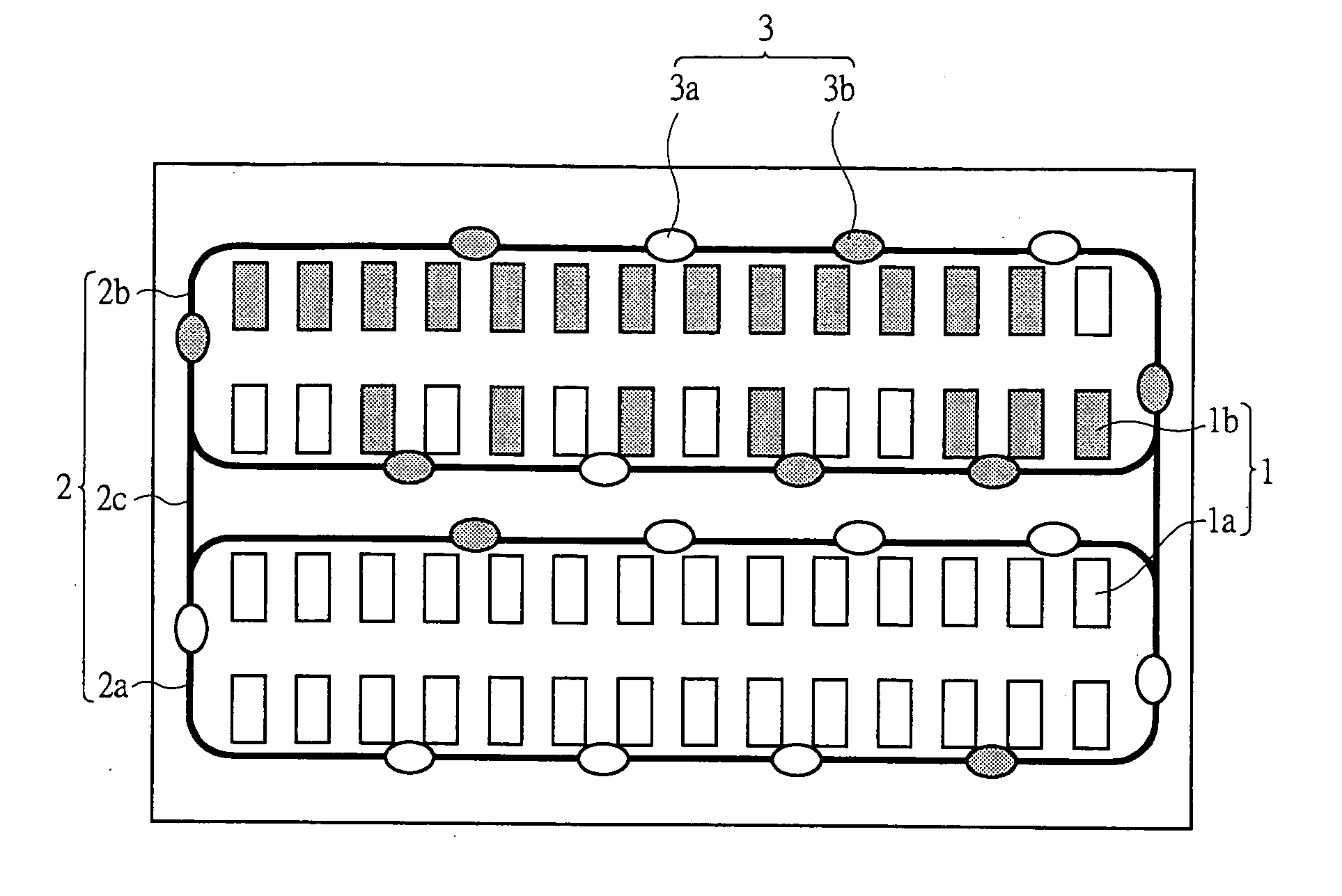
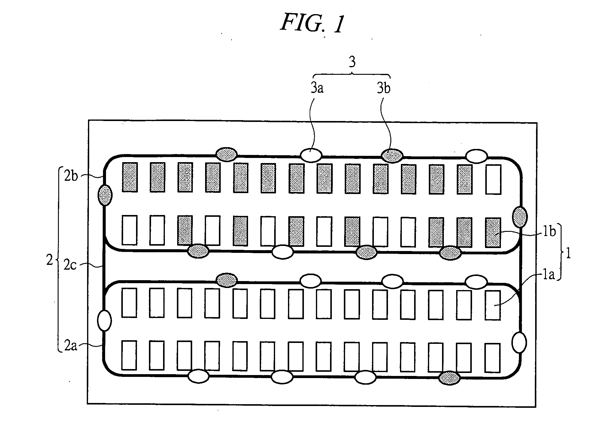
[0026] In the first embodiment, a transfer system that covers the entire space of a factory is established when constructing the factory. The number of equipments to be provided in the initial stage of constructing the factory is not so large that the entire space of the factory cannot be filled, and additional equipments will be provided when it is necessary to reinforce the ability of the factory.

[0027] More specifically, in the initial stage of constructing the factory, the number of carriers is so limited as to meet the transfer requirement. When the ability of the factory is required to be reinforced in the future, additional equipments will be provided, and simultaneously, additional carriers will also be provided. Additional carriers to be provided have to run on existing tracks and are upgraded type whose running speed is higher than that of the initially provided carriers.

[0028] As a result, new carriers and old carriers whose running performances a...

second embodiment

[0053] Second Embodiment

[0054] In the second embodiment, a transfer system is constructed and operated at a part of the factory space. More specifically, in order to reinforce the ability of the factory, the transfer system is expanded to the space where there exists no equipment, and the existing tracks are extended to realize the transfer to the expanded area. At this time, the number of carriers needs to be increased with the expansion of the transfer area as well as the improvement of the transfer ability. In this case, carriers that can run at high speed are additionally provided.

[0055] As a result, similar to the first embodiment, new carriers and old carriers each having different running performances are simultaneously provided on the same tracks, and therefore, the average transfer time of the entire factory can be reduced in comparison to the case where the carriers having the same running performance as that of the initially provided carriers are additionally provided.

[...

third embodiment

[0059] Third Embodiment

[0060] In the third embodiment, a new factory is constructed next to an existing factory that employs a transfer system. Since the objects are frequently transferred between the existing factory and the new factory, it is necessary to minimize the transfer time in the existing and new factories and that between the existing factory and the new factory. Thus, the carriers running in the existing factory and the carriers running in the new factory have to mutually move to the other factories. In the new factory, the carriers running at high speed are provided.

[0061] As a result, similar to the first embodiment, new carriers and old carriers each having different running performances are simultaneously provided on the same tracks, and therefore, the transfer time in the new factory can be significantly reduced and also the average transfer time of the entire factories including the inter-factory transfer time can be reduced in comparison to the case where the ca...


PUM


Abstract

The present invention provides a transfer technique that can improve the transfer ability when reinforcing and expanding the transfer system, with effectively using the existing system. The transfer system includes tracks that link a plurality of manufacturing equipments, a plurality of carriers having different performances that run on the tracks to transfer objects between the manufacturing equipments and the like in a factory space having a plurality of manufacturing equipments, and the plurality of carriers having different performances are simultaneously provided and run on the same tracks. The plurality of carriers are composed of old carriers and new carriers that provided together and run depending on their own performances (running performance such as running speed, acceleration/deceleration, and the like and transfer performance such as transfer speed and the like).

Description

CROSS-REFERENCE TO RELATED APPLICATION [0001] The present application claims priority from Japanese Patent Application No. JP 2003-194758 filed on Jul. 10, 2003, the content of which is hereby incorporated by reference into this application.TECHNICAL FIELD OF THE INVENTION [0002] The present invention relates to a transfer technique, more particularly, to a technique effectively applied to a transfer system in which a plurality of carriers having different performances are simultaneously driven on the same track and to a semiconductor manufacturing system using the transfer system. BACKGROUND OF THE INVENTION [0003] According to the examination by the inventors of the present invention, the following techniques are known in the conventional transfer system. [0004] For example, in an automatic transfer system in which a plurality of carriers are run on a closed track, a number of carriers that meets initially required transfer ability are provided in the initial provision stage. When...

Claims


Application Information

Patent Timeline
IPC IPC(8): G05D1/02B65G49/07H01L21/00H01L21/677
CPCH01L21/67276
Inventor WAKABAYASHI, TAKAYUKIWATANABE, SHINICHI
Owner TRECENTI TECHNOLOGIES INC
Why Eureka
Try Eureka