Laminated film for electrophotography and method for producing same, and image forming method

a technology of electrophotography and film, applied in the direction of identification means, instruments, mechanical recording, etc., can solve the problems of reducing resolution, reducing printing speed, and not being able to print individual identification information, and achieve the effect of high resolution, high quality, and convenient lamination

Inactive Publication Date: 2006-07-04
FUJIFILM BUSINESS INNOVATION CORP
View PDF25 Cites 16 Cited by
  • Summary
  • Abstract
  • Description
  • Claims
  • Application Information

AI Technical Summary

Benefits of technology

[0021]The invention provides an electrophotographic laminated film and a method for producing the same, and an image forming method, wherein the film can be readily laminated so that conventional electrophotographic device is directly used without large extent of reconstruction, images can be directly printed with high resolution on the surface of the film that is softened at a relatively low temperature, and a high quality image having sufficient light stability even in outdoor uses can be formed with good visual recognizability.
[0022]The inventors of the invention have found, through intensive studies, that the object above can be attained by controlling the surface resistance of the coating layer formed on the surface of the substrate, by selecting the material of the surface of the substrate, and by adjusting the load deflection temperature of the substrate at a predetermined temperature. The inventors also investigated a method for forming a mirror image, so that the image can be recognized as a normal image when the image is observed by naked eyes through the substrate from the opposed face to the face on which the image had been formed.
[0023]Various surface processing on the card is made possible by forming a function control layer on the surface opposed to the image forming surface with interposition of the substrate. Furthermore, transfer ability of the film can be improved by reducing the friction coefficient between the films as a result of using a polyester resin as the resin for coating the surface of the film and adding a filler in the polyester layer. Adding a ultraviolet ray absorber and an antioxidant permits light stability to be improved. A non-chlorine resin film is used as the substrate considering environmental protection, and a printing method comprising an image fixing method compatible with the use of the non-chlorine resin film has been taken into consideration.

Problems solved by technology

Therefore, such printing methods are not suitable for printing respective identification information for individuals (such as full-face pictures, names, addresses, dates of birth and various certificates).
However, although these methods enable easy printing of personal identification information, these methods still have a problem in that resolution decreases when printing speed is increased, and printing speed decreases when resolution is improved.
However, when being disposed of due to expiration of limitation period and the like, the vinyl chloride sheet has a problem of generating dioxins when disposed of by incineration with incinerators and the like.
However, because a friction coefficient between the sheets is overly large, the transfer property of the sheet becomes poor and the sheets adhere to each other.
Moreover, when insulators (sheets) have a thickness of 250 μm or more as described above, image defects may increase due to the insufficient transfer of the image forming material (toner).
Moreover, resin films having a relatively low softening point become sticky during the fixing process when such film is printed using the electrophotographic device, since the fixing temperature is higher than the softening temperature of the resin film, causing a trouble of generating winding jams in the fixing apparatus.
Furthermore, the fixing apparatus may be unnecessarily damaged by the edge of the sheet when the image forming material is offset on the fixing device or when fixing of the sheet with a thickness of 250 μm is continued.
Accordingly, a resolution comparable to that of the thermal transfer method cannot be obtained due to poor transfer of image forming materials onto the surface of the film, since the film simply made of an insulation material in JP-A No. 11-334265.
Furthermore, in the printing machine emphasizing improvements of productivity, much loss and waste inevitably arise in order to comply with urgent production or small scale production of many kinds of articles when different printing works for one or several persons are required, because the laminated sheet used is in a roll form.

Method used


Image

  • Laminated film for electrophotography and method for producing same, and image forming method
  • Laminated film for electrophotography and method for producing same, and image forming method
  • Laminated film for electrophotography and method for producing same, and image forming method

Examples


example 1

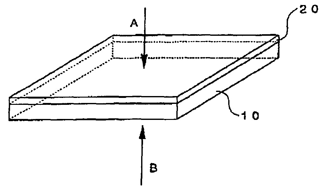
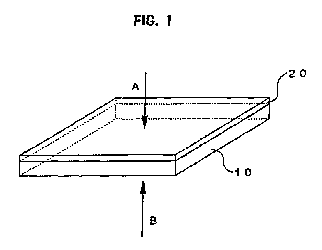
[0212]The method by which the electrophotographic laminated film (laminated film 1) of the invention is manufactured is described below with respect to each step.

Preparation of Function Control Layer Coating Liquid A-1

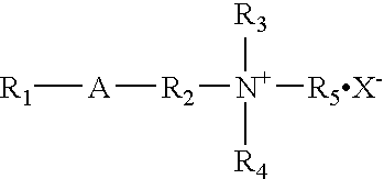
[0213]Mixed and thoroughly stirred are 10 parts of polyester resin (trade name: Thermorack P-1, manufactured by Soken Chemical & Engineering Co., Ltd., solid content in methylethyl ketone: 30% by weight) as a thermal-fusible resin, 9 parts of melamine-formaldehyde condensation fine particles (trade name: Epostar S, manufactured by Nippon shokubai Co., mean particle diameter: 0.3 μm) as a filler, 0.2 parts of a quaternary ammonium salt (trade name: Elegan 264 WAX manufactured by Nippon Oil & Fat Co.) as a surfactant, 30 parts of methylethyl ketone, and 5 parts of cyclohexanone, thereby preparing function control layer coating liquid A-1 for controlling surface luster and surface resistance.

Preparation of Image Receiving Layer Coating Liquid B-1

[0214]Mixed and thoroughly...

example 2

[0229]Laminated film 2 is produced by the same method as in Examples 1, except that a polycarbonate film (manufactured by Mitsubishi Gas Chemical Company, Inc., lead deflection temperature: 145° C., thickness: 100 μm) using bisphenol Z is used in place of the polycarbonate film using bisphenol A used in Example 1.

[0230]The laminated film 2 has a surface resistance of 1.0×10¹³ Ω / □ on the surface of the function control layer and a surface resistance of 1.30×10¹¹ Ω / □ on the surface of the image receiving layer, which are the same as those in Example 1. The results are summarized in Table 1.

example 3

Manufacture and Evaluation of Electrophotographic Laminated Film

[0231]Laminated film 3 is produced by the same method as in Examples 1. except that a polycarbonate film (manufactured by Mitsubishi Gas Chemical company, Inc., lead deflection temperature: 150° C., thickness: 100 μm) using bisphenol AP is used in place of the polycarbonate film using bisphenol A used in Example 1.

[0232]The laminated film 3 has a surface resistance of 7.5×10¹¹ Ω / □ on the surface of the function control layer and a surface resistance of 2.8×10¹¹ Ω / □ on the surface of the image receiving layer. The film is cut into A4 size, and is evaluated as in Example 1. The results are summarized in Table 1.


PUM

PropertyMeasurementUnit
load deflection temperatureaaaaaaaaaa
thicknessaaaaaaaaaa
thicknessaaaaaaaaaa

Abstract

The invention provides an electrophotographic laminated film and a method for producing the electrophotographic laminated film. The electrophotographic laminated film comprises a substrate and at least one of a coating layer and a function control means provided on a surface of the substrate. The uppermost layer of the coating layer has a surface resistance in a range of 1.0×10⁸ to 1.0×10¹³ Ω/□. The surface of the substrate preferably comprises at least one of a polycarbonate resin and a polyallylate resin. At least one of the coating layer and the function control means is preferably formed by providing a coating liquid. Further, a solvent contained in the coating liquid is preferably permits at least one of the coating layer and function control means to be formed while dissolving the surface of the substrate.

Description

CROSS REFERENCE TO RELATED APPLICATIONS[0001]This application claims benefit of and priority to Japanese Patent Application No. 2002-360432, filed on Dec. 12, 2002, which is incorporated herein by reference in its entirety for all purposes.BACKGROUND OF THE INVENTION[0002]1. Field of the Invention[0003]The present invention relates to a laminated film for electrophotography on which images are directly formed (recorded) by an electrophotographic image forming device. In particular, the invention relates to a laminated film for electrophotography that can be used by; noncontact or direct-contact information media storing personal information and image information such as cash cards with full-face pictures, identification cards for a company's staff, student identification cards, membership cards, address cards, various driving license cards and various certificates; image sheets and image display panels for personal verification used in hospitals; and labels.[0004]2. Description of t...

Claims


Application Information

Patent Timeline
Patent Type & Authority Patents(United States)
IPC IPC(8): G03G13/00G03G7/00G09F3/02
CPCG03G7/00Y10T428/31507Y10T428/31786Y10T428/31797
Inventor KOBAYASHI, TOMOOSAKURAI, KUNIOTORIKOSHI, KAORU
Owner FUJIFILM BUSINESS INNOVATION CORP
Why Eureka
Try Eureka