Electrical devices containing conductive polymers

a technology of conductive polymers and electrical devices, applied in the direction of resistor details, current responsive resistors, varistors, etc., can solve the problems of electrical continuity disruption and interface failure points, and achieve the effects of improving the electroding of conductive polymers, low contact resistance, and good electrical performan

Inactive Publication Date: 2006-01-17
LITTELFUSE INC
View PDF56 Cites 15 Cited by
  • Summary
  • Abstract
  • Description
  • Claims
  • Application Information

AI Technical Summary

Benefits of technology

[0008]We have found that improved electroding for conductive polymers can be accomplished by using foil having a combination of surface features making up the surface roughness which is in a range lower than that previously used. Until now, the primary mechanism proposed for forming a good bond between conductive polymers and metal foils has been mechanical interlocking achieved by using a rough surface on the metal foil, wherein the surface of the foil is imbedded into the conductive polymer by heating the polymer above its melting point during the electroding process. The resulting devices can have low contact resistance and good electrical performance. However, we have found that excellent performance can be achieved by fabricating devices with metal foils that have a surface roughness parameter described by the product of two characteristic measurements of surface properties. Devices made by the present invention demonstrate low electrical resistance indicating low contact resistance at the electrode-polymer interface, resistance stability following thermal cycling, and improved resistance stability during and following prolonged and repeated electrical stress.

Problems solved by technology

In a foil which has a surface which is relatively rough, it is possible that the conductive polymer composition will not fill in completely around the features of the foil surface, resulting in trapped air pockets which disrupt the electrical continuity and provide points of failure at the interface, especially under electrical stress or environmental aging.

Method used


Image

  • Electrical devices containing conductive polymers
  • Electrical devices containing conductive polymers

Examples


examples 1 to 22

Use of Low Roughness Foil to Make Low Resistance Devices

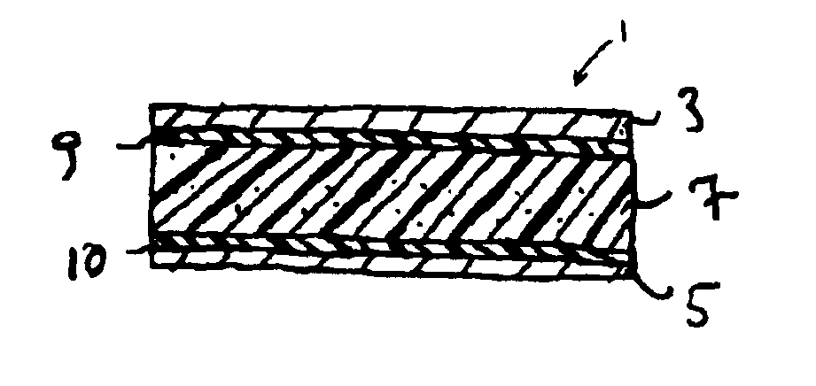
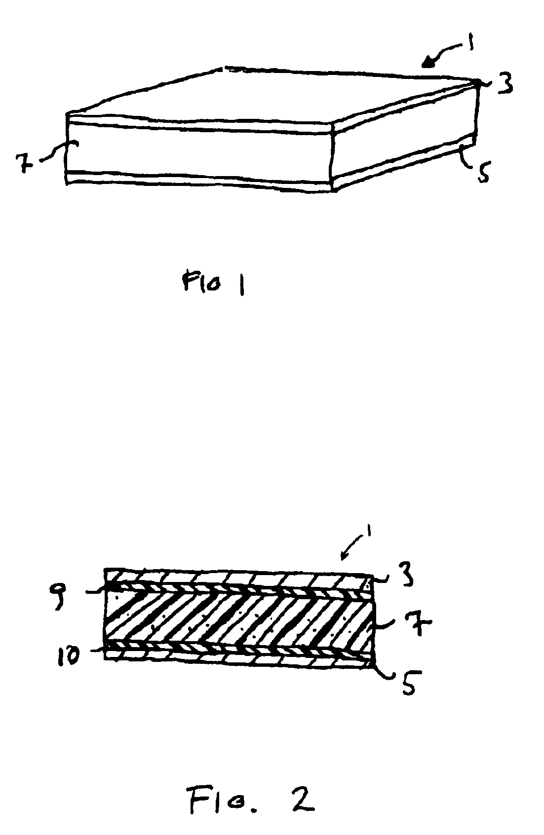
[0084]A PTC conductive polymer composition was made by extruding pellets of a melt-processed conductive polymer composition containing 43% by volume carbon black (Raven™ 430, available from Columbian Chemicals) and 57% by volume high density polyethylene (Chevron 9659, available from Chevron) into sheets approximately 0.007 inch (0.18 mm) thick. Sheets were subdivided into sections. Sheets of metal foil as described in Table I were press-laminated onto the polymer sheet sections at 200° C. at approximately 150 psi (10500 g / cm2) for 4 minutes to form laminated sheets approximately 0.010 inch (0.25 mm) thick.

[0085]Table I lists the base foil, the foil thickness, the Ra, the RD, and the Ra*RD for each foil. Foil A was a rolled nickel foil. Foil B was the same as Foil T, except the shiny side of the electrolytic copper foil with a nickel flash surface was bonded to the polymer. Foil C was the matte side of electrolytic nickel foil....

examples 23 and 24

Use of a Crosslinking Agent at the Foil-polymer Interface

[0091]Conductive polymer sheets were prepared as in Example 1, except that the conductive polymer was made from 36% (volume) Raven 430 carbon black and 64% (volume) LB832 polyethylene, available from Equistar, and was extruded to form sheets of 0.010 inch (0.25 mm) thickness. For Example 23, a 0.9% solution of dicumyl peroxide in methanol was applied twice (sequentially) to the roughened surface of the foil, prior to lamination. Lamination of foil onto both sides of the polymer sheet was performed by hot pressing at about 150 psi (10500 g / cm2) at a temperature high enough to activate the crosslinking agent (i.e. to break the peroxide bond), which was about 200° C. The foil used was type W as listed in Table II, an electrolytic nickel foil with nickel nodules on the matte side (the side bonded to the polymer), available from Fukuda Metal Foil and Powder Co., with an RD of 0.97 (MacBeth ColorChecker™ densitometer measurement) an...

example 25

Pulse Plating to Prepare Microrough Electrode Foils

[0094]One oz. (35 μm thick) electrodeposited copper foil was contacted with a dilute sulfuric acid solution (5% by volume) for two minutes, rinsed with water and then immersed in an aqueous bath at 20 to 25° C. with a pH of 2.5 to 3.0 with the following composition (all values in mole / l): nickel sulfate, 0.09; ammonium sulfate, 0.11; sodium sulfate, 0.17; sodium chloride, 0.17; boric acid, 0.20. A conformal layer of nickel was initially plated onto the matte side of the copper foil at a steady DC current density of 2.1 mA / cm2 for 3 minutes. This was immediately followed by a second nickel plating step carried out using square-wave DC pulses using 11% duty cycle at 100 Hz and a peak pulse current density of 210 mA / cm2. Nickel was plated under these pulsed conditions for a total of 3 minutes. A third pulsed plating step was similarly conducted except that the frequency and duty cycle were increased to 200 Hz and 33%, respectively, and...


PUM

PropertyMeasurementUnit
Raaaaaaaaaaa
Raaaaaaaaaaa
resistanceaaaaaaaaaa

Abstract

An electrical device in which an element composed of a conductive polymer composition is positioned in contact with the first surface of a metal electrode, the first surface having a center line average roughness Ra and a reflection density RD, the product Ra times RD being 0.5 to 1.6 μm. The conductive polymer composition preferably exhibits PTC behavior. In a second embodiment an electrical device has an element composed of a conductive polymer composition in contact with the first surface of a metal electrode produced by providing a base metal foil having an Ra of at most 0.45 μm and depositing material onto the base metal foil to form a first surface having a product of Ra times RD of at least 0.14 μm. Other embodiments include electrical devices with metal electrodes made by pulse plating processes, and metal electrodes made by electrodeposition under diffusion-limited conditions. The electrical devices may be circuit protection devices and have improved electrical and physical properties.

Description

CROSS-REFERENCE TO RELATED APPLICATIONS[0001]This application is a continuation application of commonly assigned application Ser. No. 09 / 606,825, filed Jun. 28, 2000, now U.S. Pat. No. 6,593,843, the disclosure of which is incorporated herein by reference.BACKGROUND OF THE INVENTION[0002]1. Field of the Invention[0003]This invention relates to electrical devices comprising conductive polymer compositions, to methods of making such devices, and to circuits comprising such devices.[0004]2. Introduction to the Invention[0005]Electrical devices comprising conductive polymer compositions are well known. Such devices comprise an element composed of a conductive polymer. The element is physically and electrically connected to at least one electrode suitable for attachment to a source of electrical power. The factors determining the type of electrode used include the specific application, the configuration of the device, the surface to which the device is attached, the resistance of the dev...

Claims


Application Information

Patent Timeline
Patent Type & Authority Patents(United States)
IPC IPC(8): H01C7/13H01C7/00H01C1/14H01C7/02
CPCH01C7/027H01C1/1406
Inventor BECKER, PAUL N.JANKOWSKI, ORIONWALSH, CECILIA A.
Owner LITTELFUSE INC
Why Eureka
Try Eureka