Electronic controlled fuel injection apparatus of internal combustion engine

a fuel injection and electric control technology, applied in the direction of engine starters, electric control, muscle operated starters, etc., can solve the problems of reducing the output of the power generator, reducing the size of the storage means and the power generator, and achieving the effect of reducing the backup battery size, improving the loading performance, and simple starting operation of the recoil starter

Inactive Publication Date: 2005-01-13
HONDA MOTOR CO LTD
View PDF8 Cites 21 Cited by
  • Summary
  • Abstract
  • Description
  • Claims
  • Application Information

AI Technical Summary

Benefits of technology

[0018] Further, in accordance with the present invention, it is possible to obtain an excellent loading performance with respect to a general engine-working machine because of a synergy of a simple starting operability of the recoil starter and a downsizing of the backup battery. The nickel cadmium battery is charged after starting the engine on the basis of its good charging performance, and it is possible to stably supply a holding power for starting to the next engine start.
[0019] Even in the case that the engine fails to be started, since the fuel pump is driven at a time when the revolution number of the engine is lowered to be equal to or less than the first revolution number, it is possible to quickly operate the starting apparatus so as to again start the engine starting operation.
[0020] In accordance with the present invention, it is possible to stably supply the electricity to each of the electronic control devices by restricting a peak value of electricity consumption such that the operations of the electric controlled devices required for the fuel injection do not coincide one other. In particular, since the structure is made such as to operate proximate to the region of the maximum amplitude so as to efficiently obtain the electricity in spite that an effective value of the output of the power generator is largely fluctuated in correspondence to the change of the revolution number of the engine, it is possible to easily secure the required electricity even in the case that the revolution number of the engine is low and the effective value of the output is small.
[0021] Further, in accordance with the present invention, since the electricity can be efficiently obtained, it is possible to use the single-phase two-pole power generator so as to secure the electricity. Accordingly, it is possible to downsize the coil-winding portion of the power generator, and a space capable of arranging the other devices or the like is generated within the power generator as well as the cost reduction. Therefore, a freedom in layout of the devices is increased.
[0022] Since the fuel injection valve is driven in synchronous with the halfwave waveform, it is possible to easily set the fuel injection timing in correspondence to the output waveform of the power generator.
[0023] Further, it is possible to obtain an excellent general-purpose loading performance with respect to a general engine-working machine, owing to a simple starting operability of the recoil starter.

Problems solved by technology

On the other hand, the output of the power generator greatly comes short at a time of starting the engine.
This restrain of electricity consumption results in a downsizing both of a storage means and a power generator.

Method used


Image

  • Electronic controlled fuel injection apparatus of internal combustion engine
  • Electronic controlled fuel injection apparatus of internal combustion engine
  • Electronic controlled fuel injection apparatus of internal combustion engine

Examples


Embodiment Construction

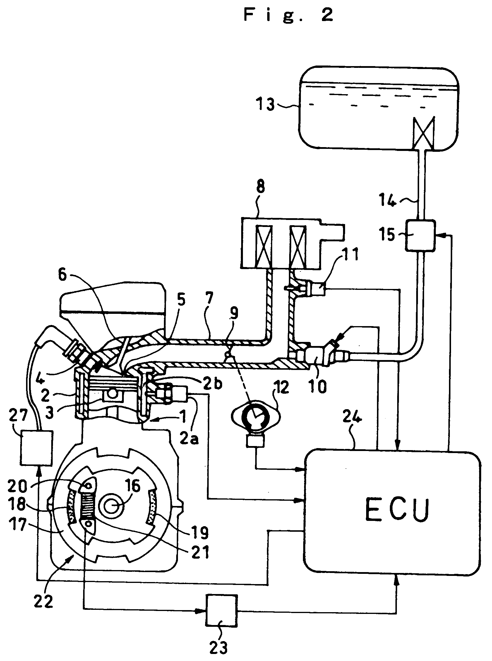
[0030] A description will be in detail given below of the present invention with reference to the accompanying drawings. FIG. 2 is a view showing a structure of an engine power generating apparatus in accordance with an embodiment of the present invention. In the drawing, a piston 3 and an ignition plug 4 are disposed in a cylinder 2 of an engine 1. An intake valve 6 is provided at an intake port 5 positioned to an upper portion of the cylinder 2, and the intake port 5 is communicated with an atmospheric air via an intake pipe 7 and an air cleaner 8. A throttle valve 9 is provided between the intake port 5 and the air cleaner 8 on the intake pipe 7, and a fuel injection valve 10 an intake temperature sensor 11 for detecting an intake temperature are disposed in an upstream side of the throttle valve 9. An opening degree of the throttle valve 9 is detected by a throttle opening degree sensor 12. A passage 2b through which cooling water is circulated is formed to surround the wall of ...


PUM


Abstract

The invention intends to downsize a general-purpose engine generator and make operability thereof easy. A backup battery (233) is provided for the generator (22). The battery supplies electricity to an electronic controlled device such as a fuel pump for starting the engine. When the engine (1) carries out a rating operation, electricity is supplied from the generator (22). When the engine speed is in a low speed range, only a pump (15) is driven. When the engine speed is exceeds the low speed range, the pump (15) is stopped, and an injectors (10) and (27) are driven to be prevented from lapping over each other. When the engine speed reaches a high-speed range, the pump (15) is again driven. Electricity consumption at a time of starting is restricted by driving the electronic controlled devices at different timings until the engine (1) executes a self-sustaining.

Description

BACKGROUND OF THE INVENTION [0001] 1. Field of the Invention [0002] The present invention relates to an electronic controlled fuel injection apparatus of an internal combustion engine, and more particular to an electronic controlled fuel injection apparatus of a relatively compact internal combustion engine which can be started on the basis of a manual operation without using a starter motor. [0003] 2. Description of the Related Art [0004] There has been known an electronic controlled fuel injection apparatus constituted by a fuel injection valve disposed in an intake system of an internal combustion engine (hereinafter, refer simply to as an “engine”), and a control apparatus which controls a valve opening time of the fuel injection valve in correspondence to an operation state of the engine so as to adjust a fuel injection quantity. In the conventional electronic controlled fuel injection apparatus, a battery stably supplying a sufficient electricity is generally provided for oper...

Claims


Application Information

Patent Timeline
Patent Type & Authority Applications(United States)
IPC IPC(8): F02D37/02F02D41/06F02D41/30F02N3/00
CPCF02D37/02F02D41/062F02N3/00F02D2400/06F02D41/3082
Inventor TAMECHIKA, TAKAOTOIDA, NAOYASHINOGI, YOSHIHISANISHIDA, KAZUTOMOMIYASHITA, KAZUMI
Owner HONDA MOTOR CO LTD
Why Eureka
Try Eureka