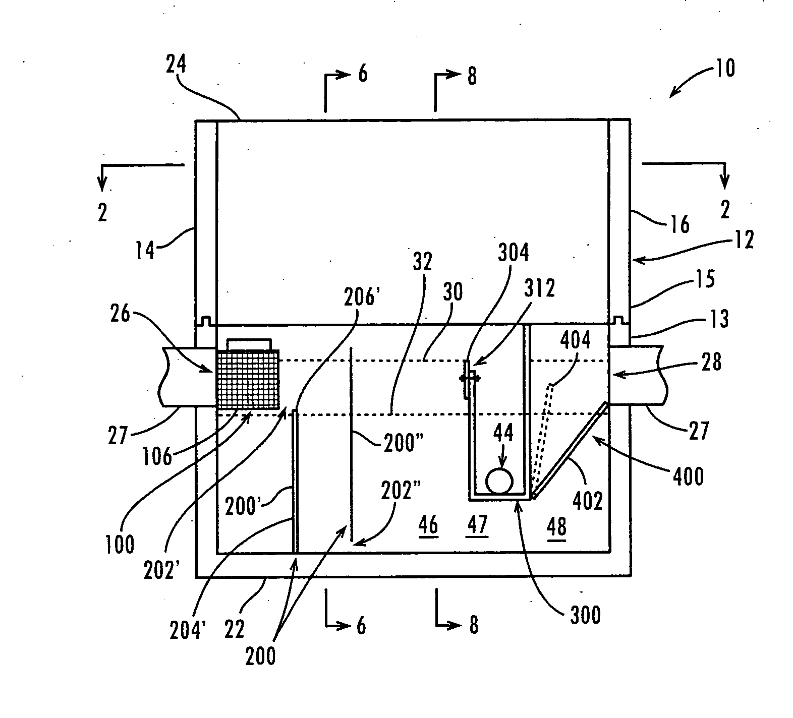
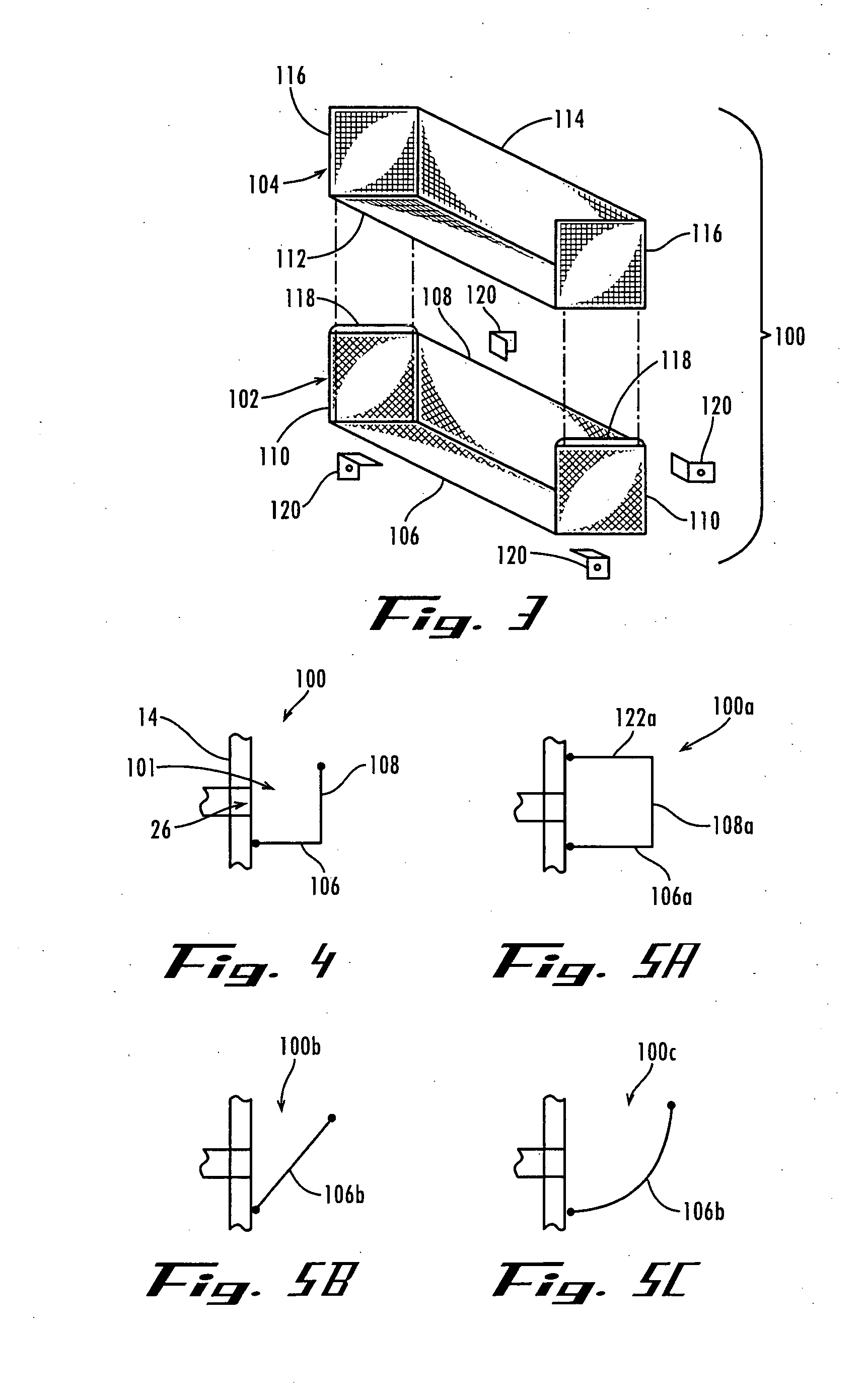
[0012] In an exemplary embodiment of the present invention, the screen is positioned at or above the at-rest
water level so that the screen retains some of the pollutants, allows the water to pass through it, and suspends the retained pollutants above the at-rest
water level. In this way, the suspended retained pollutants are kept dry when there is no storm so that they do not waterlog, deteriorate, and pass through the screen. The screen can be, for example, basket-shaped but with an open side adjacent the inlet.
[0013] The baffles are each configured and positioned in the chamber to form at least one gap through which the water may flow around the baffle. In this way, the water flows around the baffles in a longer flow
route through the chamber, without flowing any faster. Preferably, the collective flow area through the baffles is significantly greater than the flow area of the inlet to cause the linear speed of the flow to slow substantially while maintaining the volume of the flow constant. This increases the
residence time of the water in the chamber, which encourages
settling of some of the pollutants.
[0015] In addition, the baffles may have apertures in them that permit at least some of the liquid to pass through them. In this way, the apertured baffles disperse the water, which further encourages
settling of some of the pollutants.
[0017] In addition, the bottom of the collection reservoir may be positioned above the chamber floor to permit the water to flow under the collection reservoir. In this way, the
water flow route through the chamber is increased to further encourage settling of some of the pollutants.
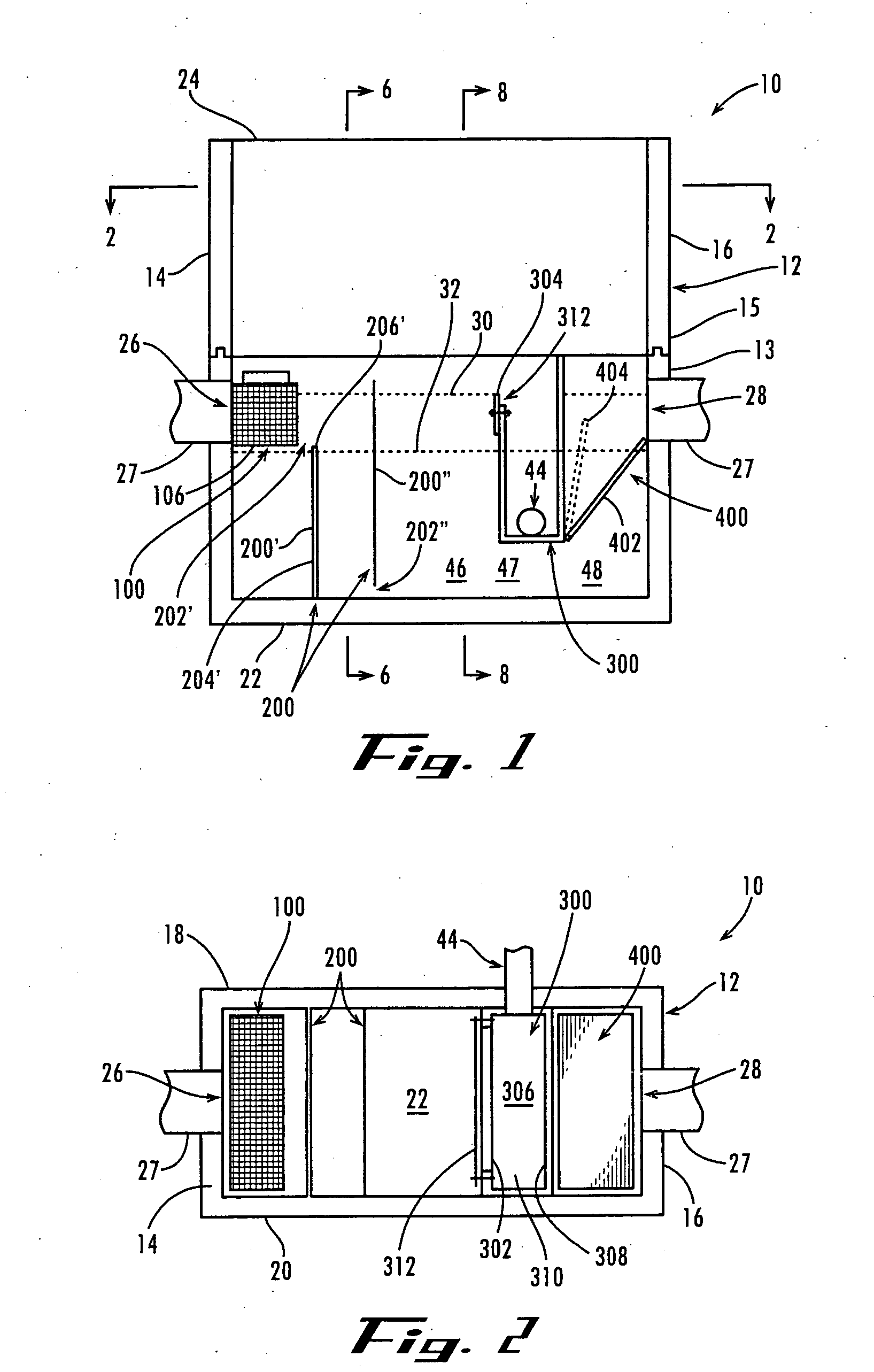
[0020] In this exemplary embodiment, the screen, baffle, reservoir, and pivotal filter
filtration stages cooperate to provide a significant increase in performance over conventional pollution traps. In particular, the screen suspends at least some of the miscellaneous debris above the at-rest
water level, the baffles increase water
residence time in the chamber to encourage settling of the particulate matter, the collection reservoir skims at least some of the floating matter into it but allows the water to flow under it, and the pivotal filter filters out at least some of the suspended clay. It will be understood by those skilled in the art that these
filtration stages can be used in this or other configurations for separating other pollutants from other liquids.
[0022] Accordingly, the pollution trap stays on-line and routes all the storm-water runoff through it, instead of bypassing or overflowing during larger-than-typical storms. In particular, the pollution trap collects floating hydrocarbons and particulate matter during larger-than-typical storms, when more of these pollutants are carried by the storm water. Additionally, the pollution trap reduces waterlogging of absorbent miscellaneous debris and better induces settling of particulate matter, thereby providing improved filtration of pollutants from the storm water. Furthermore, the pollution trap is cost-efficient to build, install, and maintain.

