Method of controlling electronic controlled thermostat

a technology of electronic control and thermostat, which is applied in the direction of electric control, lighting and heating apparatus, instruments, etc., can solve the problems of difficult to determine the best set water temperature for the vehicle, and inability to ensure constant heat radiation quantity, etc., to achieve high degree of precision, low cost, and low cost

Active Publication Date: 2005-01-13
NIPPON THERMOSTAT CO LTD
View PDF9 Cites 79 Cited by
  • Summary
  • Abstract
  • Description
  • Claims
  • Application Information

AI Technical Summary

Benefits of technology

[0027] In this invention, the poor water temperature control characteristics that have been a problem in the past can be eliminated by performing linear control of the valve under specified conditions that conform much more closely to actual conditions, so that the cooling water is maintained at the required temperature, thus making it possible to realize high cooling water temperature tracking characteristics with a high degree of precision at a low cost. As a result, the cooling water temperature can be [controlled] appropriately and efficiently in accordance with the load of the engine in the engine operating conditions, and this system is also superior in terms of response characteristics and stability of the cooling water temperature. Moreover, there is no danger of overshooting, undershooting, hunting or the like, and the cooling water temperature can be appropriately controlled to a high water temperature or low water temperature. In addition, a more reliable improvement in fuel consumption can be achieved, and this can be achieved throughout substantially the entire range of operating conditions.
[0028] Here, “correction for the amount of heat radiation of the element” is a correction in which the amount of heat radiation from the thermo-element into the cooling water is predicted, and the power is increased or decreased so that heat corresponding to this amount of heat radiation is made up by the heat-radiating element in order to ensure that heat corresponding to the amount of heat escaping by heat radiation is securely absorbed by the expansion body (WAX), thus eliminating the effects of heat radiation. If such a correction is performed, the water temperature control characteristics such a hunting, water temperature control width and the like can be improved.

Problems solved by technology

As was described above, problems that must be considered when controlling the cooling water temperature in an electronically controlled thermostat include the “response characteristics from the setting of the powering of the actuator to the variation in the water temperature”.
Specifically, in conventional electronically controlled thermostat control methods, various factors such as undershooting, overshooting, hunting, rate of heat exchange of the cooling water and the like have on the time period extending from the powering of the actuator to the opening of the valve so that the actual water temperature shifts to the target water temperature; accordingly, a considerable time is required for this operation.
Conventionally, furthermore, the electrical circuit used to power the PTC used as a heat generating device mounted on the abovementioned actuator has been a constant-voltage circuit; accordingly, since the resistance value of the PTC varies with the temperature, a constant heat radiation quantity cannot be ensured.
Furthermore, in automobiles, the following problem also arises: namely, because of individual differences in the manner in which the driver rides, the layout of the cooling water circulation system in each vehicle, differences in thermostats and the like, it is difficult to determine the best set water temperature for the vehicle in the design stage; accordingly, it is desirable that attention also be given to such points.

Method used


Image

  • Method of controlling electronic controlled thermostat
  • Method of controlling electronic controlled thermostat
  • Method of controlling electronic controlled thermostat

Examples


Embodiment Construction

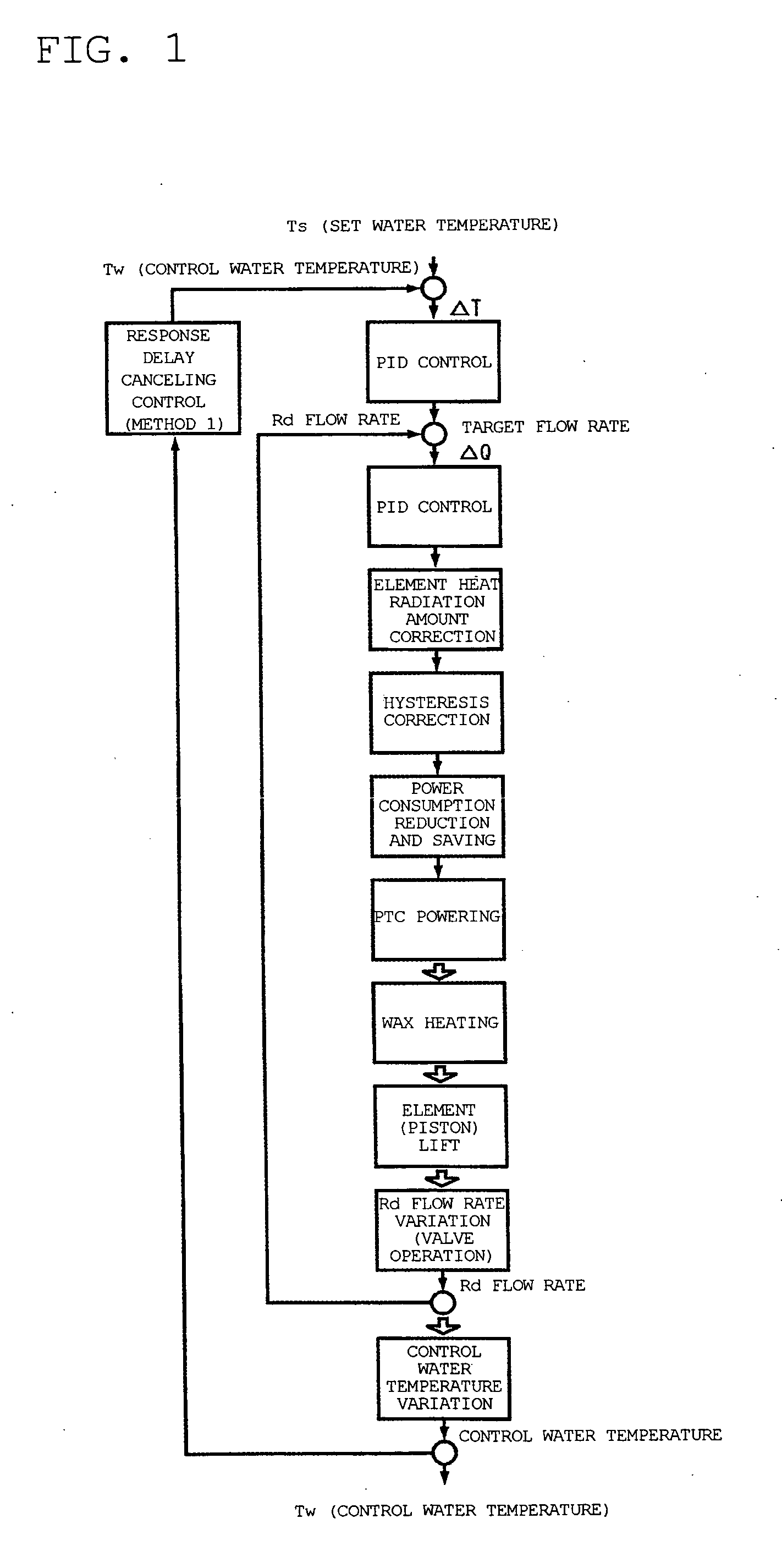
[0057]FIGS. 1 and 2 show one embodiment of the electronically controlled thermostat control method of the present invention.

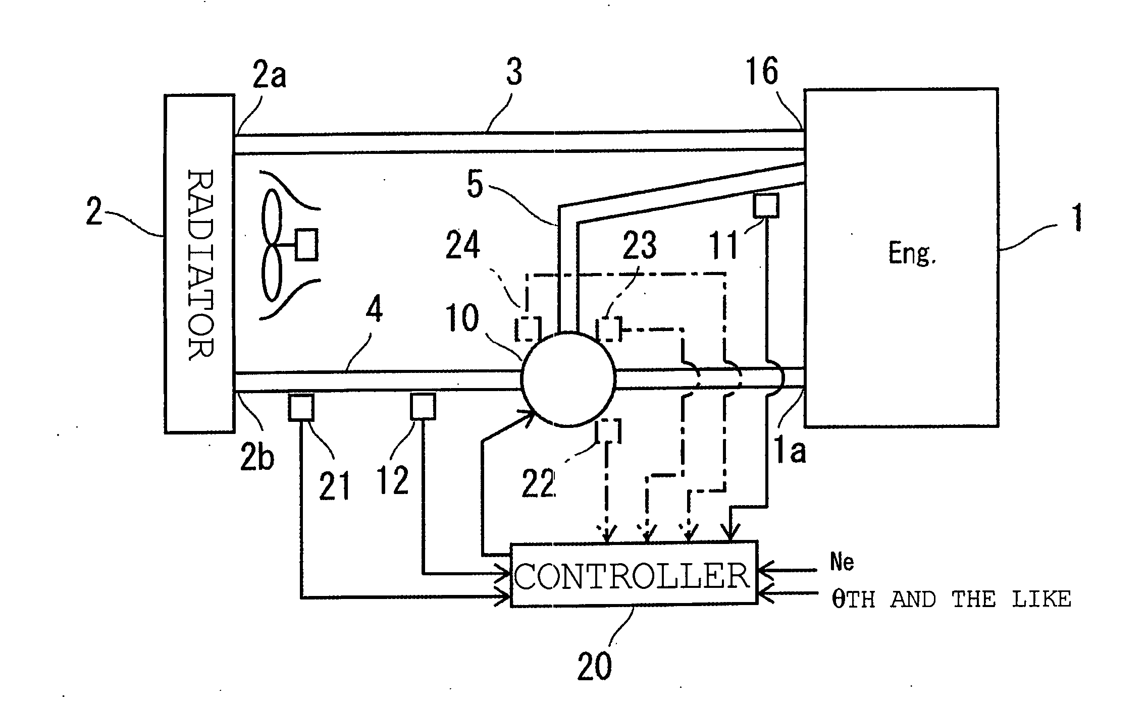
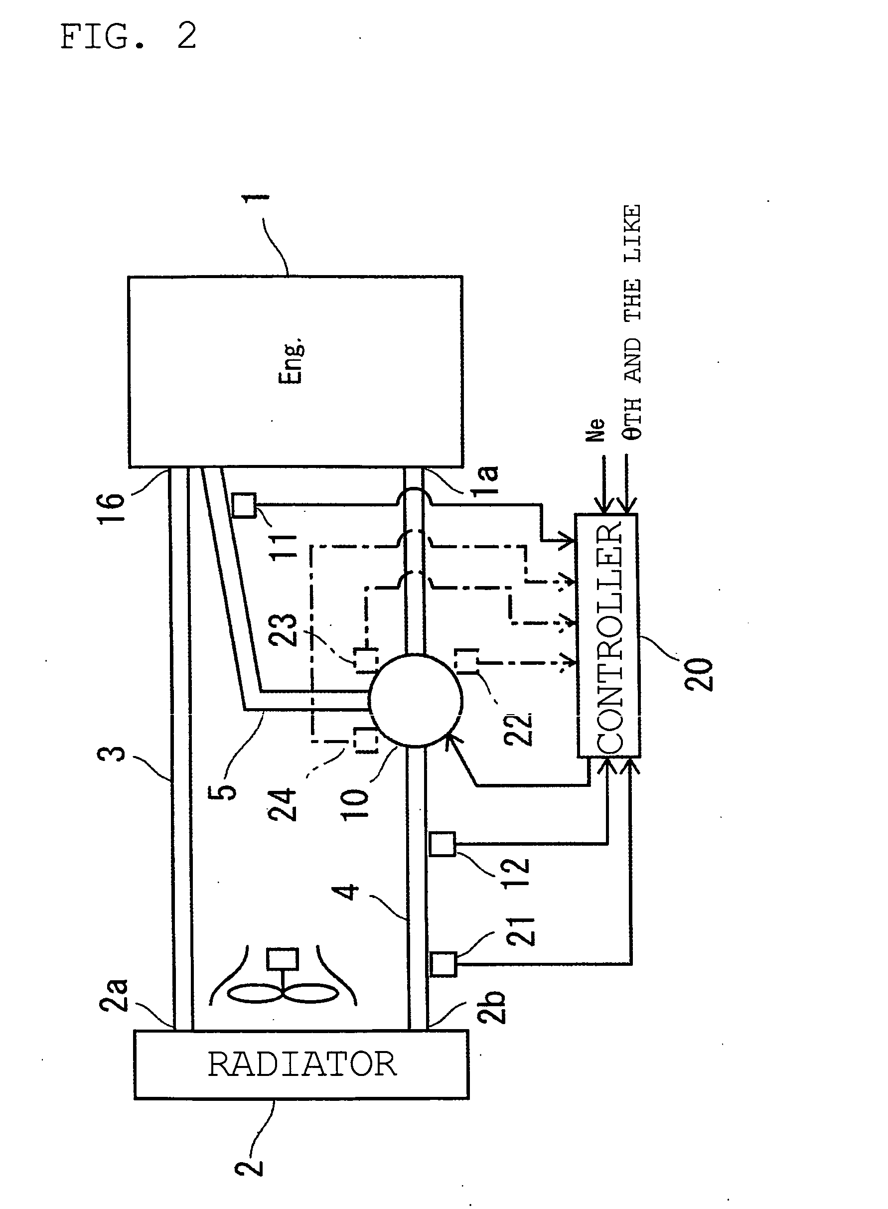
[0058] In these figures, a description will first be presented below on the basis of FIG. 2, which shows an overall outline of the cooling water temperature control system of an automobile engine that includes an electronically controlled thermostat.

[0059] In FIG. 2, 1 indicates an automobile engine used as the engine [in the present system]; a universally known cooling water passage (not shown in the figures) is formed inside this engine 1.

[0060]2 indicates a heat exchanger, i.e., a radiator (Rd). A universally known cooling water passage is also formed inside this radiator 2; furthermore, the cooling water inlet pat 2a and cooling water outlet part 2b of the radiator 2 are connected to cooling water passages 3 and 4 that circulate cooling water between [the radiator 2] and the abovementioned engine 1.

[0061] The cooling water passage is constructed from an...


PUM


Abstract

An electronically controlled thermostat control method is obtained which makes it possible to eliminate the response delay from the time that the required cooling water temperature is set to the time that the actual cooling water temperature reaches the set water temperature by controlling the flow rate, and to realize high cooling water temperature tracking characteristics with a high degree of precision at a low cost. The method of the present invention is characterized in that in an electronically controlled thermostat which is used to control the cooling water temperature of an engine, and which comprises an actuator that can arbitrarily vary the degree of valve opening without depending only on the actual cooling water temperature, the actuator is controlled by the control controller, which has means for calculating the elapsed time from the powering of the actuator to the variation of the water temperature for predicting the water temperature after the elapsed time when the cooling water temperature is controlled to an arbitrarily set water temperature, and the actuator is controlled in advance in accordance with the above-described predicted water temperature.

Description

TECHNICAL FIELD [0001] The present invention relates to an electronically controlled thermostat control method for which allows the arbitrary variation of the degree of valve opening without depending on the actual temperature alone in an engine cooling water temperature control system which variably sets the cooling water temperature in accordance with the load of an engine used in an automobile or the like (hereafter referred to as an “engine”). Included is, for example, a system in which a temperature sensing part disposed in a heat-sensing part, and a system in which a valve is controlled by a motor. BACKGROUND ART [0002] In automobile engines, water cooling type cooling systems using a radiator are generally used in order to cool the engine. Conventionally, furthermore, in cooling systems of this type, a control valve, e.g., a thermostat, which controls the amount of cooling water that is circulated on the radiator side so that the temperature of the cooling water that is intro...

Claims


Application Information

Patent Timeline
Patent Type & Authority Applications(United States)
IPC IPC(8): F02D45/00F01P7/16G05D23/13G05D23/19
CPCF01P7/167F01P2023/00F01P2023/08F01P2025/06F01P2025/32F01P2025/36G05D23/1951F01P2025/62F01P2025/64F01P2031/00F01P2070/04G05D23/1393F01P2025/60F01P2037/02
Inventor SUDA, NORIOSUDA, HIROSHISANO, MITSUHIROTSUKAMOTO, DAISUKEABURAKAAWA, MASAHIRO
Owner NIPPON THERMOSTAT CO LTD
Why Eureka
Try Eureka