
Sensor assembly for sensing angular position

a sensor and angular position technology, applied in the field of motor vehicle sensors, can solve the problems of sensor failure, affecting the integrity of the sinusoidal waveform of the magnetic flux, and undesired sliding contact of the sensor,

Inactive Publication Date: 2005-01-13
DELPHI TECH INC
View PDF20 Cites 55 Cited by
  • Summary
  • Abstract
  • Description
  • Claims
  • Application Information

AI Technical Summary

Benefits of technology

will be more apparent from the following...

Problems solved by technology

Although resistive-film sensors are commonly used, such sensors, however, would undesirably require a sliding contact.
These sensors, unfortunately, may be sensitive to eccentric placement of various components that make up the sensor, such as eccentricity of the sensed target.
Moreover, if a steel ring with slits or similar structure is placed around the magnet, then such a structure tends to create discontinuities along the periphery of the magnet, thus affecting the integrity of the sinusoidal waveform of the magnetic flux.
Unfortunately, such a substantial linearity may often be achieved just through the use of costly and complex signal processing circuitry that consumes valuable real estate in size-constrained applications.

Method used


Image

  • Sensor assembly for sensing angular position
  • Sensor assembly for sensing angular position
  • Sensor assembly for sensing angular position

Examples


Embodiment Construction

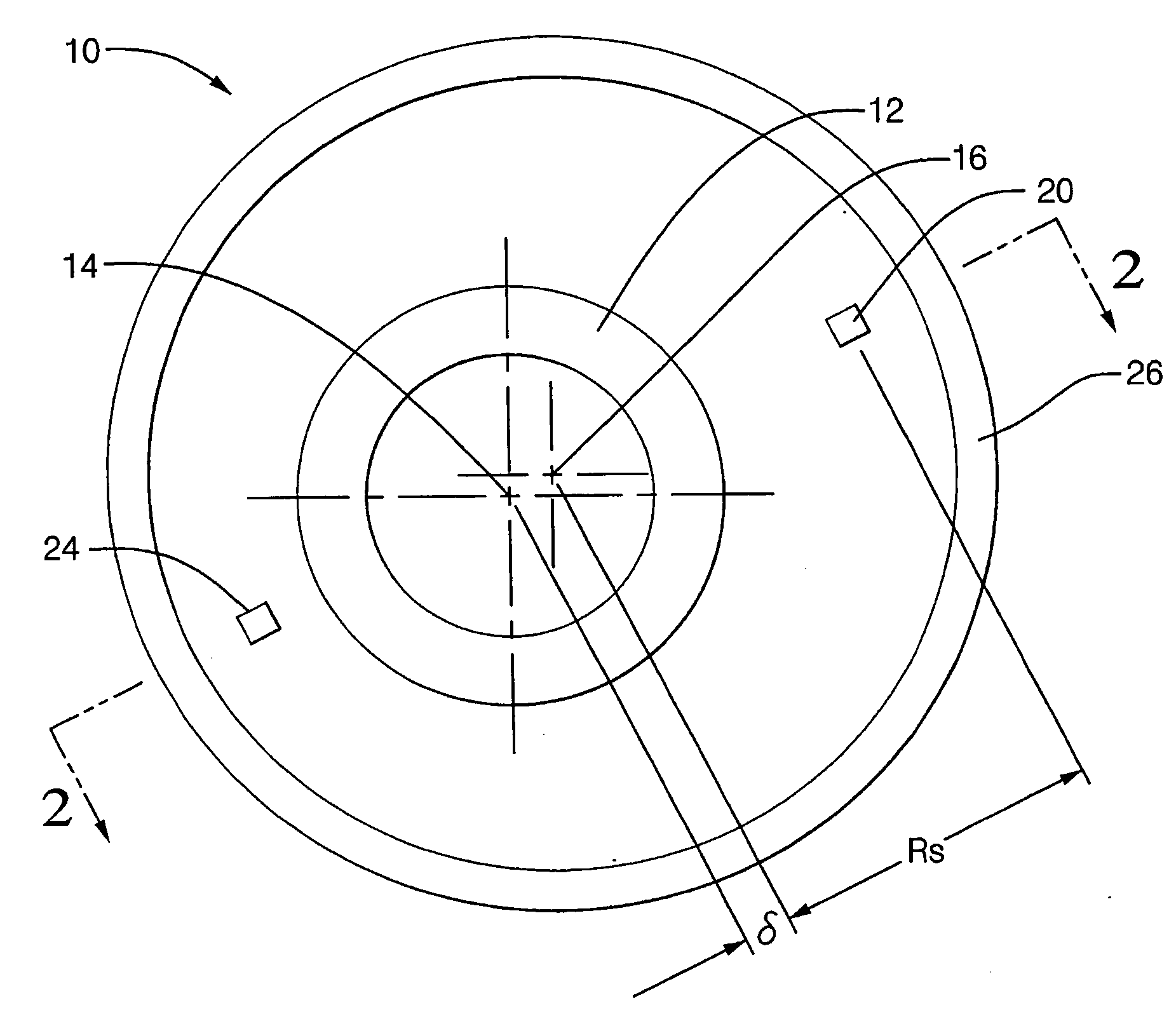
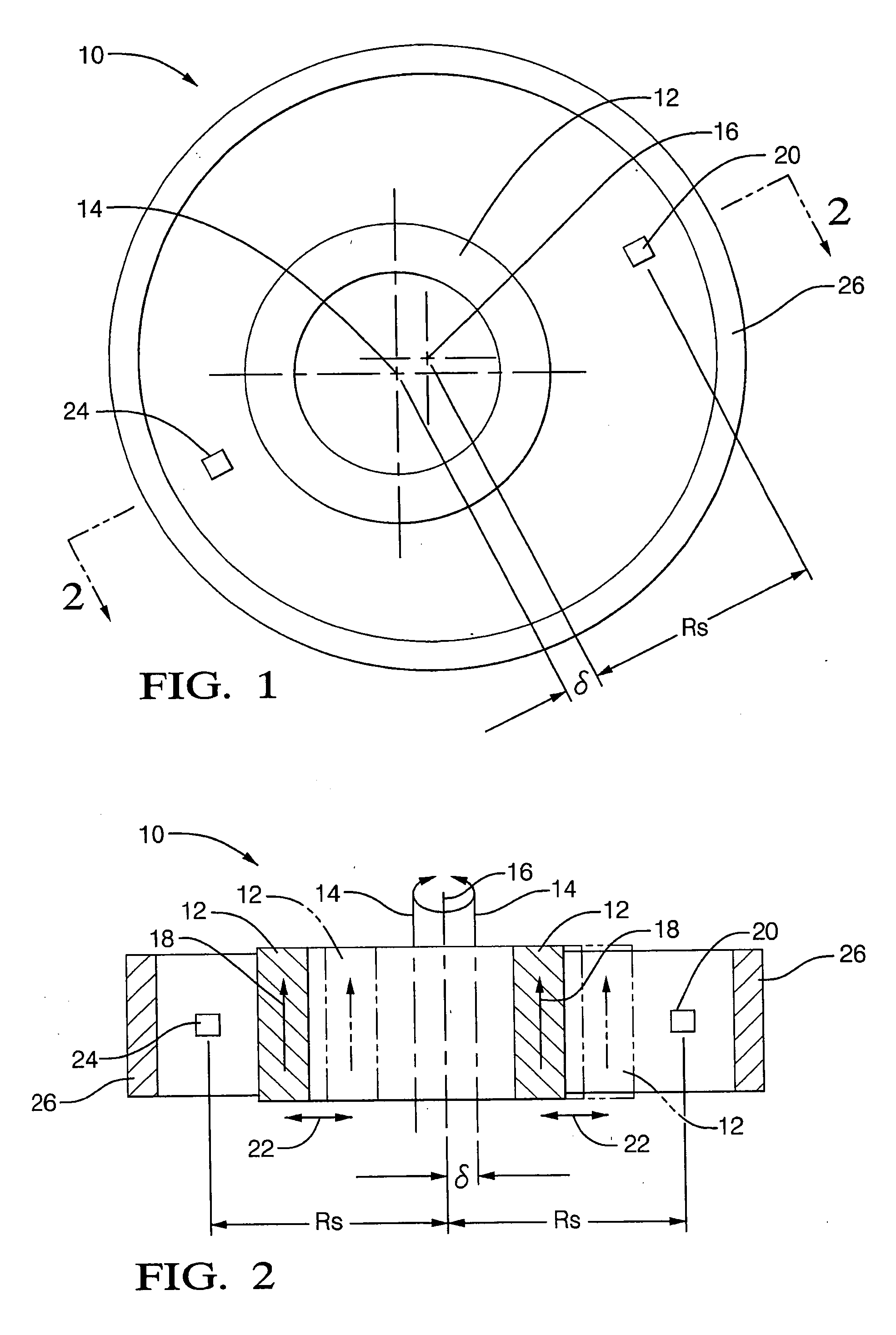
An exemplary embodiment of a sensor assembly 10 embodying aspects of the present invention is shown in FIG. 1 (top view), and in FIG. 2 (cross-sectional view). The sensor assembly 10 includes a cylindrical magnet 12. The cylindrical magnet defines a geometric axis 14, e.g., an axis corresponding to the physical (e.g., cylindrical) configuration of the magnet. Magnet 12 is positioned to rotate around an axis of rotation 16. The axis of rotation is placed at some non-zero distance 6 from the magnet axis 14. That is, the axis of rotation 16 and the geometric axis 14 are non-coincident with one another. In one preferred embodiment, the cylindrical magnet is magnetized generally axially, as represented by arrows 18 in FIG. 2. A second preferred embodiment with a generally radial magnetization is described below in the context of FIGS. 7 and 8. It will be understood that either deviating by a few degrees from axial (or radial) magnetization, or appropriately combining axial and radial di...


PUM


Abstract

A sensor assembly for sensing angular position of an object is provided. The assembly may comprise at least one magneto-sensing element having a first axis of rotation. The assembly may further comprise a magnet having a second axis of rotation. At least one of the magnet and the magneto-sensing element are rotatable relative to the other. The respective axes of rotation of the magneto-sensing element and the magnet are non-coincident with respect to one another. The magnet is magnetized along one of the following directions: an axial direction and a radial direction.

Description

FIELD OF THE INVENTION The present invention is generally related to motor vehicle sensors, and, more particularly, the present invention is directed to a sensor assembly for contactlessly detecting the angular position of a rotatable object. BACKGROUND OF THE INVENTION Modern motor vehicles are equipped with numerous sensors that provide detailed information regarding the operation of the vehicle. This information may be displayed for a driver or it may be processed and provided to various vehicle control systems. For example, an analog position sensor can provide both position information and outputs that can be used to drive an electric motor or other electromechanical devices. Many of these devices may be driven by sinusoidal excitations that vary as a function of position. Consequently, an analog position sensor having an output that varies sinusoidally with position could be used to generate absolute angular positions as may be used in an electrical power steering system to...

Claims


Application Information

Patent Timeline
IPC IPC(8): G01B7/30G01D5/14G01D5/16
CPCG01D5/145G01D2205/73
Inventor LEQUESNE, BRUNO P. B.OMEKANDA, AVOKI M.SCHROEDER, THADDEUS
Owner DELPHI TECH INC
Features
  • Generate Ideas
  • Intellectual Property
  • Life Sciences
  • Materials
  • Tech Scout
  • Unparalleled Data Quality
  • Higher Quality Content
  • 60% Fewer Hallucinations
Learn More