Angular sensor with a magneto-electric transducer and a magnetic deflection device

a technology of magneto-electric transducer and angular sensor, which is applied in the direction of galvano-magnetic devices, galvano-magnetic hall-effect devices, instruments, etc., can solve the problems of increasing the size of the stators, increasing the manufacturing cost of angular sensors, and unlikely miniaturization of angular sensors

Inactive Publication Date: 2006-04-18
AISIN SEIKI KK
View PDF18 Cites 66 Cited by
  • Summary
  • Abstract
  • Description
  • Claims
  • Application Information

AI Technical Summary

Problems solved by technology

Notwithstanding, with the known angular sensor mentioned above, because two stators forming the sensor are configured to be semicircle mating along an internal diameter of the annular magnet, the configuration is complicated, the siz

Method used


Image

  • Angular sensor with a magneto-electric transducer and a magnetic deflection device
  • Angular sensor with a magneto-electric transducer and a magnetic deflection device
  • Angular sensor with a magneto-electric transducer and a magnetic deflection device

Examples


first embodiment

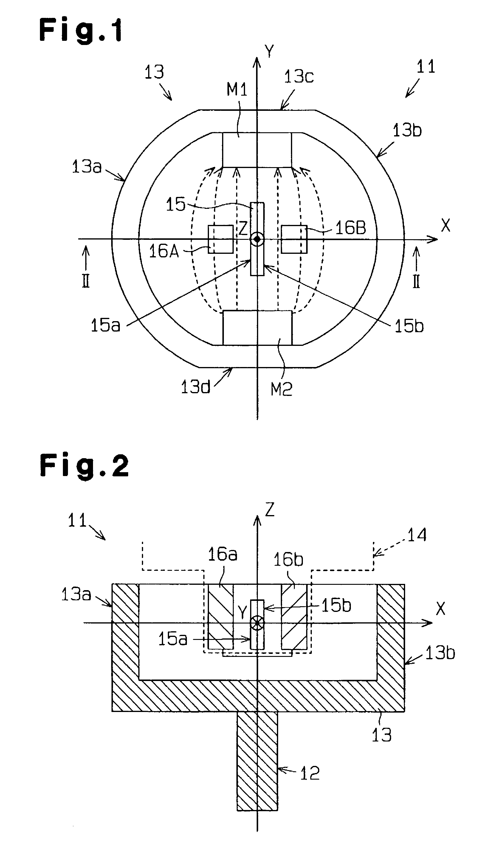
[0018]Two embodiments of an angular sensor is explained with reference to the illustrations in the drawing figures. the angular sensor according to the present invention is explained referring to FIGS. 1–4.

[0019]FIG. 1 is a plane view of an angular sensor 11 and FIG. 2 is a cross-sectional view of FIG. 1 taken on line II—II of FIG. 1. The angular sensor 11 is assembled to a stator 14 and a rotational shaft 12 and positioned relatively rotatable to the stator 14 for detecting a rotational angle of the rotational shaft 12. The angular sensor 11 includes a cylindrical yoke (i.e., rotor) 13 made of magnetic material, a first magnet M1 which is configured to be rectangular and installed on an internal peripheral surface of the cylindrical yoke 13, and a second magnet M2 which is configured to be rectangular and installed on an internal peripheral surface of the cylindrical yoke 13 opposing the first magnet M1. A magneto-electric transducer element (i.e., hall element) 15 is fixed on the ...

second embodiment

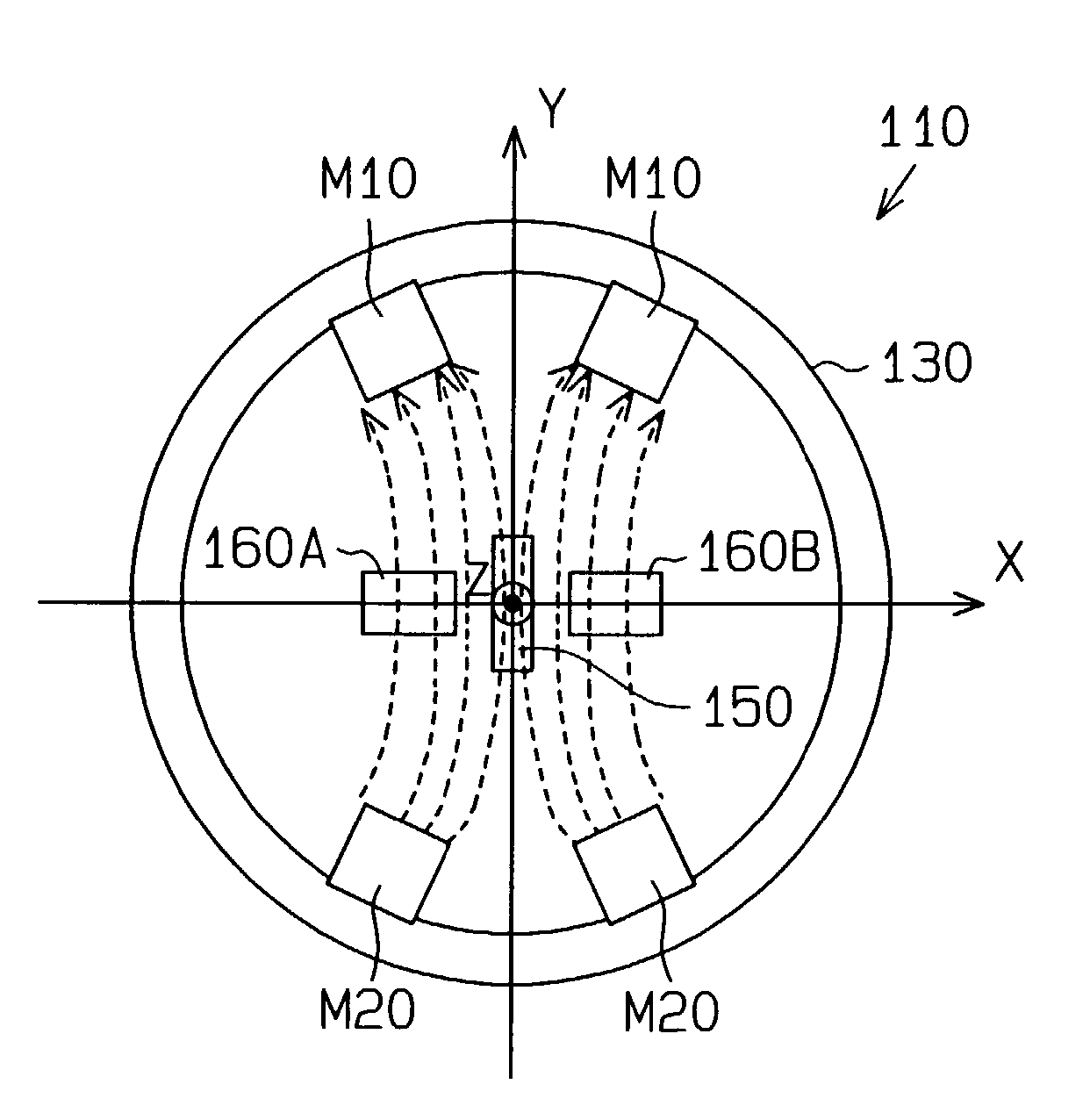
[0030]A second embodiment of the angular sensor of the present invention is explained referring to FIG. 5. With an angular sensor 110 according to the present invention, the construction of magnets M10, M20, the configuration of a cylindrical yoke 130, and dimension of deflection yokes 160A, 160B are different compared to the first embodiment of the angular sensor shown in FIGS. 1–4. Because the other constructions of the angular sensor 110 is the same with the angular sensor 11 of the first embodiment, the explanation is omitted.

[0031]As shown in FIG. 5, the first magnet M10 includes two magnets and each piece of first magnet M10 is applied to the internal peripheral surface of the cylindrical yoke 130 keeping a predetermined distance in the peripheral direction from each other. The second magnet M20 also includes two magnets and each piece of the second magnet M20 is applied to the internal peripheral surface of the cylindrical yoke 130 keeping a predetermined distance in the peri...


PUM


Abstract

An angular sensor which enables to obtain an output signal proportional to a relative rotational angle with low manufacturing cost and with miniaturized size. An angular sensor which includes a first magnet and a second magnet fixed to a rotation body, magnetic flux sensing surface is fixed to the stator to be positioned in magnetic field between the first magnet and the second magnet and perpendicular to magnetic sensing direction for sensing a magnetic flux, a magneto-electric transducer element for outputting an electric signal corresponding to a magnetic sensing direction element of the magnetic density, deflection yokes. The deflection yokes are positioned facing the magnetic flux sensing surfaces. The deflection yokes are positioned within a range of three quarters of a distance between the first magnet and the second magnet in X-axis direction and one half of a distance between the first magnet and the second magnet in Y-axis direction.

Description

[0001]This application is based on and claims priority under 35 U.S.C. § 119 with respect to Japanese Application No. 2001-230555 filed on Jul. 30, 2002, the entire content of which is incorporated herein by reference.[0002]1. Filed of the Invention[0003]The present invention relates to an angular sensor. More particularly, the present invention pertains to an angular sensor for detecting a relative rotational angle between a stator and a rotor using a magneto-electric transducer element for converting the sensed magnetic flux density into an electric signal.[0004]2. Background of the Invention[0005]A known angular sensor is disclosed in Japanese Patent No. 2920179. This known angular sensor includes an annular magnet having different magnetic poles on internal surface and external surface thereof respectively. The annular magnet rotates in a main magnetic pole clearance between two magnetic parts. One of the magnetic parts corresponds to two stators forming a secondary magnetic pol...

Claims


Application Information

Patent Timeline
IPC IPC(8): G01B7/30G01B7/00G01D3/02G01D5/12G01D5/14G01D5/20
CPCG01D5/145G01D3/02
Inventor KATO, YUKIHIROTAGUCHI, KENICHITAGAWA, SATORU
Owner AISIN SEIKI KK
Why Eureka
Try Eureka