Magnetic gradiometer incorporating global feedback

a global feedback and magnetic field technology, applied in the direction of three-component magnetometers, instruments, material magnetic variables, etc., can solve the problems of 1/f noise, difficult to measure the field near the threshold of sensitivity in the presence of earth's field, and expensive and time-consuming processes

Inactive Publication Date: 2002-01-15
QINETIQ LTD
View PDF4 Cites 68 Cited by
  • Summary
  • Abstract
  • Description
  • Claims
  • Application Information

AI Technical Summary

Benefits of technology

(iv) the adaptive signal processing means comprise means for minimising the total energy, E, of the sensor outputs subject to a constraint, whereby the constraint determines which of one or more magnetic field gradient components is generated.
The system utilises an adaptive signal processing technique to achieve high levels of balance. The application of this technique to magnetic detection with gradiometer systems is unknown. The employment of adaptive signal processing is essential to allow the system to utilise a scheme of global (or overall) magnetic field feedback. For a system from a moving platform, this provides sufficient dynamic range for the system to operate in the earth's field whilst maintaining high levels of balance. Furthermore, it also provides the advantage that it prohibits the ambient external field impinging directly on the sensors. Furthermore, it relaxes the mechanical rigidity constraints for the system.

Problems solved by technology

Measurement of fields near to the threshold of sensitivity in the presence of the earth's field present many difficulties.
Balancing is usually achieved by adjustment in special calibration rigs under laboratory conditions and is an expensive and time consuming process.
Furthermore, as a large background field is incident on the sensor, currents are induced in the structure which give rise to 1 / f noise and can give rise to hysteresis problems.
Furthermore, as well as the difficulties in balancing, each sensor requires a very large dynamic range (better than 1 part in 10.sup.9) if it is to be operable on a moving platform, as is often required.
In addition, there is still the problem that the field is incident on the structure.
However, the problems of stability, non-linearity, uniformity of feedback and the need to calibrate and fix the balance are not overcome.
It is the difficulty of accurately subtracting the sensor outputs which give rise to many of the problems.

Method used


Image

  • Magnetic gradiometer incorporating global feedback
  • Magnetic gradiometer incorporating global feedback
  • Magnetic gradiometer incorporating global feedback

Examples


Embodiment Construction

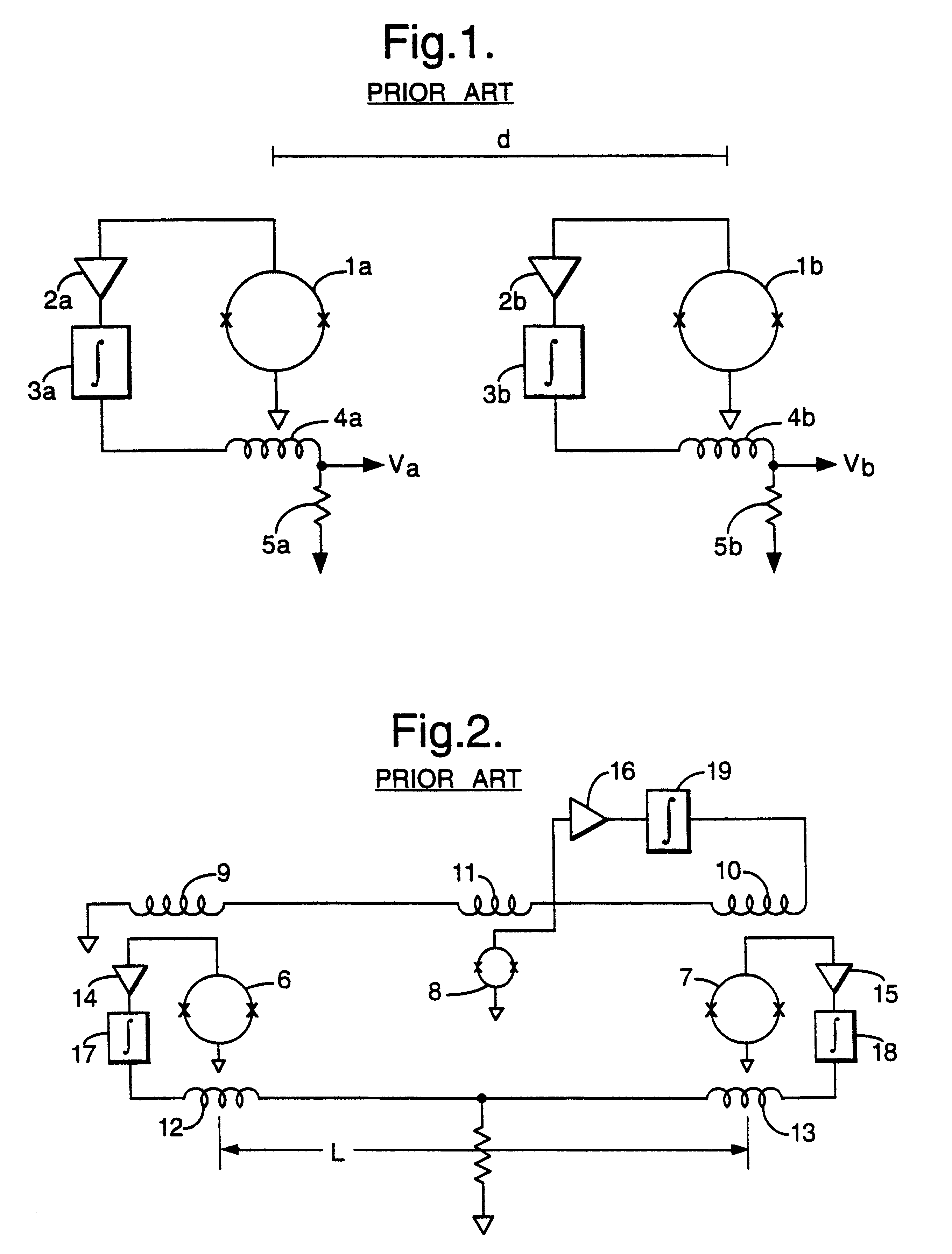
Referring to FIG. 1, a conventional configured gradiometer for measuring the magnetic field gradient may comprise two magnetometers 1a, 1b, typically SQUID magnetometers, separated by a distance d (baseline distance), whereby each magnetometer 1a, 1b measures the magnetic field at its particular location. The gradiometer also comprises amplifiers 2a,2b and integrators 3a,3b, feedback coils 4a,4b and resistors 5a,5b, having the same resistance, for providing a correction current producing a field equal and opposite to that of the external magnetic field incident on the SQUIDs. Voltages Va, Vb are output from the device corresponding to the magnetic field at each of the SQUID magnetometers 1a, 1b respectively. The difference between the two voltages, Va-Vb, provides an approximation of the magnetic field gradient.

The two magnetometer gradiometer shown in FIG. 1 has a large common mode signal of the two SQUIDs, arising from the earth's magnetic field and requires an almost impossibly l...


PUM


Abstract

A gradiometer for measuring properties of a magnetic field and in particular, for measuring magnetic field gradient components, comprising at least two magnetic sensors wherein at least two of the magnetic sensors are arranged to sense the magnetic field component in substantially the same direction. The magnetic sensors may be super conducting quantum interference device (SQUID) magnetometers, Hall probes, flux gates or magneto-resistive magnetometers. The gradiometer also includes a computer processor loaded with an adaptive signal-processing algorithm, for performing adaptive signal balancing of the magnetometer outputs. In a preferred embodiment the gradiometer may comprise at least eight magnetometers in a three-dimensional arrangement, and a set of three orthogonal global feedback coils, one for each direction x, y, z, such that the five independent magnetic field gradient components may be measured. The gradiometer may also be used to measure second or higher order magnetic field gradient components.

Description

1. Field of the InventionThe invention relates to apparatus for measuring magnetic field information, and may be used in particular for determining components of magnetic field gradient. The system may be used to detect magnetic field gradients of the order of 100 fT m.sup.-1 from a moving platform in the background of the earth's magnetic field (approximately 70 .mu.T).2. Discussion of Prior ArtSQUID (superconducting quantum interference devices) magnetometers are extremely sensitive devices which can measure vector components of magnetic field as small as 10.sup.-9 times the ambient field of the earth. Measurement of fields near to the threshold of sensitivity in the presence of the earth's field present many difficulties. Geomagnetic noise and man-made noise, for example, are always dominant. Furthermore, unless the SQUIDs are rigidly mounted, even minute motions in the earth's field will be reflected as gross changes in output and therefore it is often more useful to sense the g...

Claims


Application Information

Patent Timeline
Patent Type & Authority Patents(United States)
IPC IPC(8): G01R33/022G01R33/02
CPCG01R33/022G01R33/0206
Inventor KEENE, MARK NSATCHELL, JULIAN S
Owner QINETIQ LTD
Why Eureka
Try Eureka