
Image forming system, image forming apparatus, operation control method for image forming apparatus, and control program for image forming apparatus

Inactive Publication Date: 2005-01-13
KYOCERA DOCUMENT SOLUTIONS INC
View PDF3 Cites 15 Cited by
  • Summary
  • Abstract
  • Description
  • Claims
  • Application Information

AI Technical Summary

Benefits of technology

[0006] It is an object of the present invention to provide an image forming system, an image forming apparatus,

Problems solved by technology

In such a case, while the color printer may be selected to accomplish the entire jobs therein, it essentially involves a problem of slower print speed and higher cost than those in the monochrome printer.
Alternatively, while the entire jobs may be accomplished by using the monochrome printer, the data being originally intended to be color-printed will be monochrome-printed, or the print jobs will be undesirably performed against a user's expectation.
However, this method will undesirably force the user to handle a complicated and cumbersome operation.
However, this conventional image forming system is subject to use the particular dedicated machine or collator to mix the respective recording materials from the color and monochrome printers with images formed thereon.
Thus, the requirement of incorporating the dedicated machine or collator leads to undesirably complexified structure and increased system cost.

Method used


Image

  • Image forming system, image forming apparatus, operation control method for image forming apparatus, and control program for image forming apparatus
  • Image forming system, image forming apparatus, operation control method for image forming apparatus, and control program for image forming apparatus
  • Image forming system, image forming apparatus, operation control method for image forming apparatus, and control program for image forming apparatus

Examples


first embodiment

[0025] [First Embodiment]

[0026] (Overall Structure of Image Forming System)

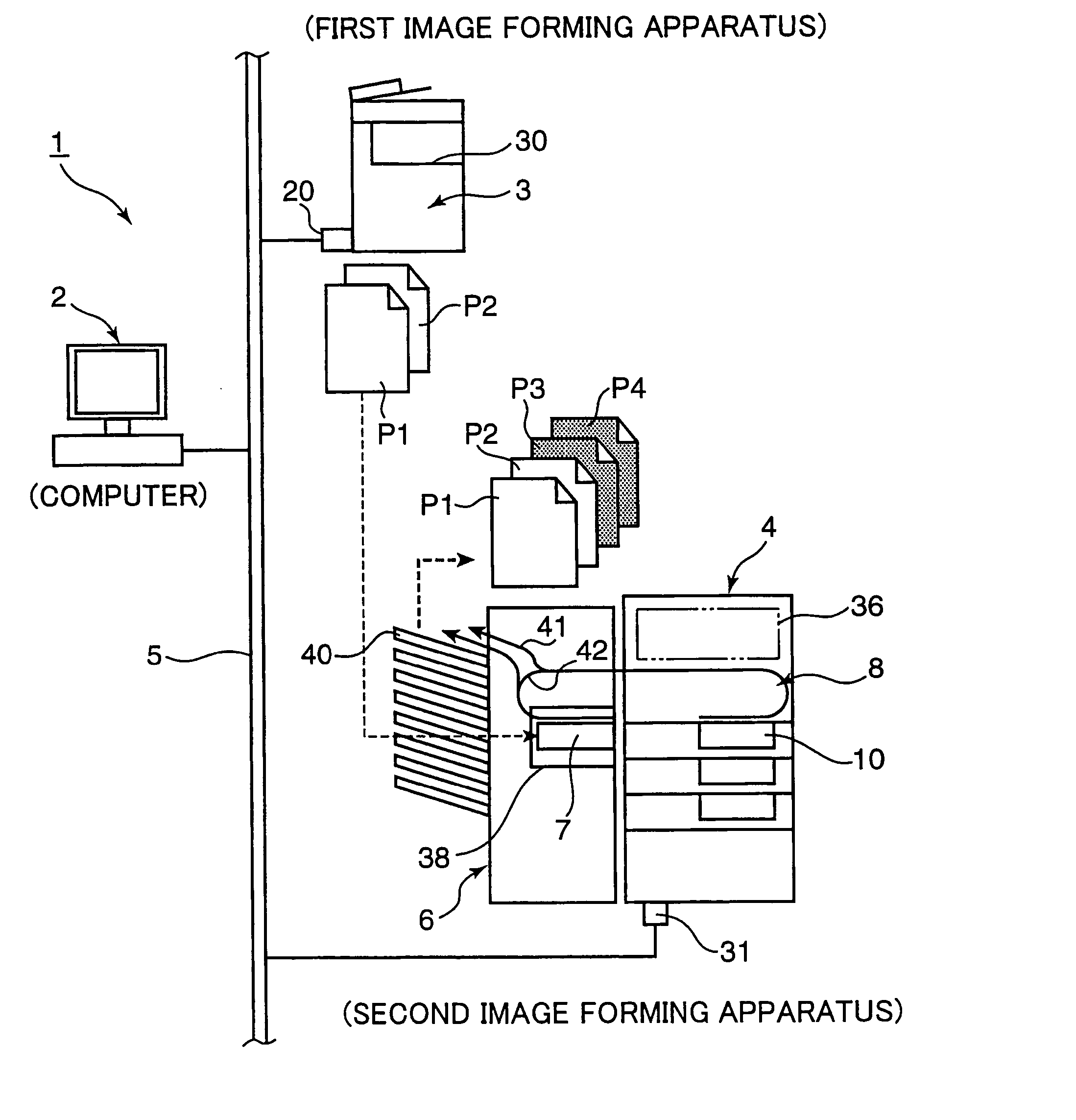
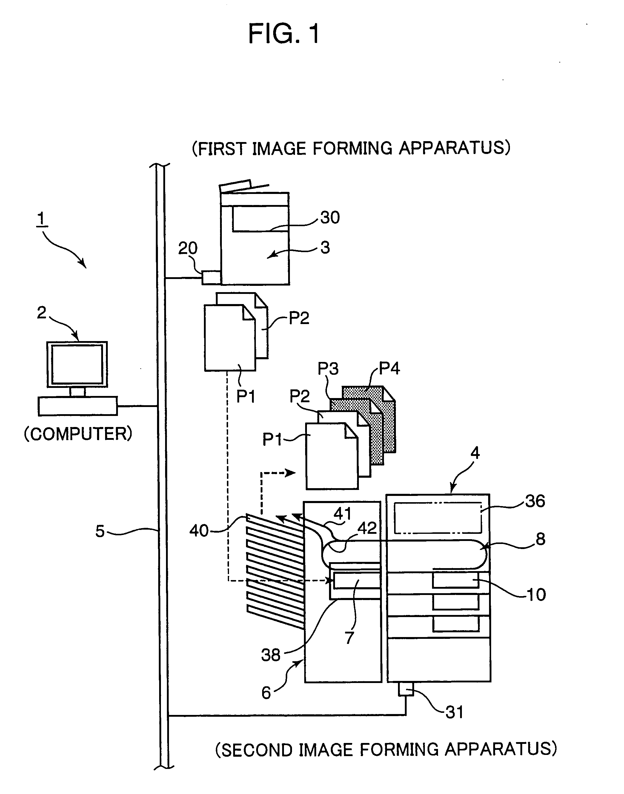
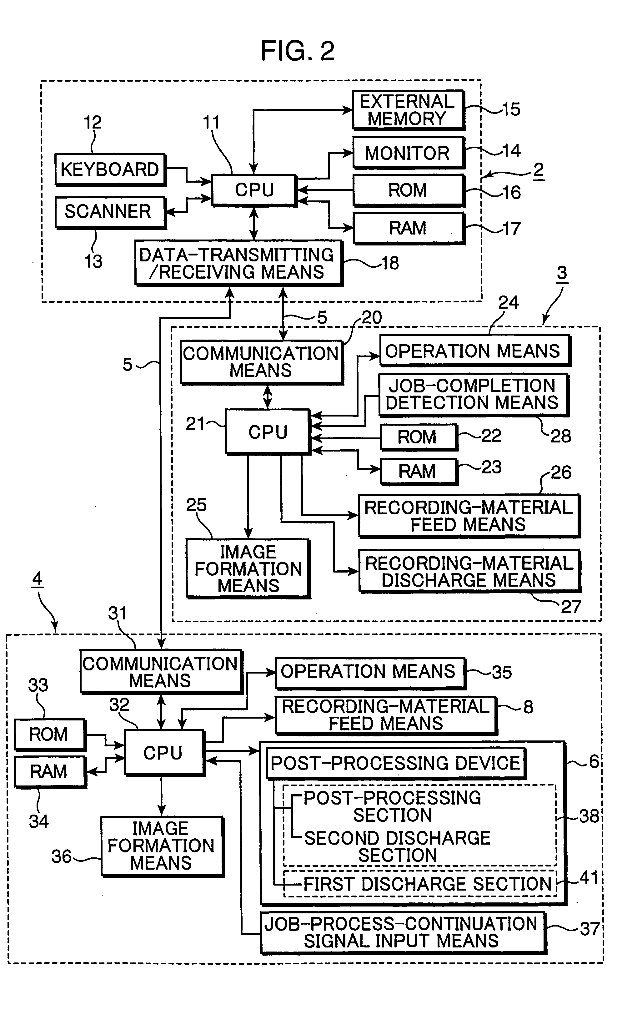
[0027]FIG. 1 schematically shows the overall structure of an image forming system 1 according to a first embodiment of the present invention. As shown in this figure, the image forming system 1 comprises one or more computers 2, and a plurality of image forming apparatuses (printers, copiers, facsimile machines, multifunctional complex machines having a network scanner function and others) 3, 4, which are connected with each other via a network 5. The computer 2 can designate one or more of the image forming apparatuses 3, 4, and instruct the image forming apparatuses 3, 4, to perform a specific job. The image forming system 1 of the present invention is configured to allow the computer 2 to acquire information about the operational state of each of the image forming apparatuses 3, 4. The image forming system 1 of the present invention includes both an image forming apparatus 3 capable of performing only mon...

second embodiment

[0050] [Second Embodiment]

[0051] (Overall Structure of Image Forming System)

[0052]FIG. 7 schematically shows the overall structure of an image forming system 1 according to a second embodiment of the present invention. As shown in FIG. 7, the image forming system 1 comprises one or more computers 2, and a plurality of image forming apparatuses (printers, copiers, facsimile machines, multifunctional complex machines having a network scanner function and others) 3, 4, which are connected with each other via a network 5. The computer 2 can designate one or more of the image forming apparatuses 3, 4, and instruct the image forming apparatuses 3, 4, to perform a specific job. The image forming system 1 of the present invention is configured to allow the computer 2 to acquire information about the operational state of each of the image forming apparatuses 3, 4. The image forming system 1 of the present invention includes both an image forming apparatus 3 capable of performing only monoch...

third embodiment

[0076] [Third Embodiment]

[0077] (Overall Structure of Image Forming System)

[0078]FIG. 12 schematically shows the overall structure of an image forming system 1 according to a third embodiment of the present invention. As shown in FIG. 12, the image forming system 1 comprises one or more computers 2, and a plurality of image forming apparatuses (printers, copiers, facsimile machines, multifunctional complex machines having a network scanner function and others) 3, 4, which are connected with each other via a network 5. The computer 2 can designate one or more of the image forming apparatuses 3, 4, and instruct the image forming apparatuses 3, 4, to perform a specific job. The image forming system 1 of the present invention is configured to allow the computer 2 to acquire information about the operational state of each of the image forming apparatuses 3, 4. The image forming system 1 of the present invention includes both an image forming apparatus 3 capable of performing only monoch...


PUM


Abstract

An image forming system is disclosed, in which recording materials P1, P2 with monochrome images formed in a first image forming apparatus 3 capable of performing only monochrome printing are set in a post-processing tray 7 of a post-processing device 4 in a second image forming apparatus 2 capable of performing color printing, and either one of operations: one of feeding recording materials P3, P4 through the recording-material feed means 8; another of feeding the recording materials P1, P2 from the post-processing tray 7, is automatically selected according to page numbers. First and second discharge sections 41 and 38 of the post-processing device 6 are operable to serializably discharge the color-printed recording materials P3, P4 and the recording materials P1, P2 onto a recording-material discharge tray 40, respectively, so as to mix monochrome pages and color pages together in order of page number. The present invention can provide an image forming system with simplified structure at a low cost.

Description

FIELD OF THE INVENTION [0001] The present invention relates to an image forming system comprising a plurality of image forming apparatuses (copiers, printers, facsimile machines and / or combinations thereof and a computer which are connected with each other via a network, wherein the computer is operable to control the operation of the image forming apparatuses so as to perform printing on a recording material. The present invention also relates to an image forming apparatus for use in such an image forming system, an operation control method for the image forming apparatus, and a control program for the image forming apparatus. BACKGROUND OF THE INVENTION [0002] There has heretofore been known an image forming system comprising a computer and an image forming apparatus, such as a copier, a printer or a facsimile machine, which are connected with each other via a network, wherein the computer is operable to transmit various job data created therein, for example, to a color or monochr...

Claims


Application Information

Patent Timeline
IPC IPC(8): G06F3/12G06F11/30G06F15/00H04N1/32H04N1/50
CPCH04N1/233H04N1/2353H04N1/32545H04N1/32502H04N1/32529H04N1/2361
Inventor KISHIGAMI, TAKASHI
Owner KYOCERA DOCUMENT SOLUTIONS INC
Learn More