LED lamps and LED driver circuits for the same

Active Publication Date: 2005-01-13
ALLTEMP PROD CO LTD
View PDF28 Cites 148 Cited by
  • Summary
  • Abstract
  • Description
  • Claims
  • Application Information

AI Technical Summary

Benefits of technology

[0009] The present invention provides LED inspection lamps that are suitable for causing fluorescent materials to fluoresce to assist in the detection of such fluorescent materials. Said in

Problems solved by technology

Furthermore, inspection lamps with incandescent, halogen or mercury vapor light sources required filters to remove undesired visible wavelengths that interfere with seeing the fluorescence of visible materials, while LEDs often produce litt

Method used


Image

  • LED lamps and LED driver circuits for the same
  • LED lamps and LED driver circuits for the same
  • LED lamps and LED driver circuits for the same

Examples


second embodiment

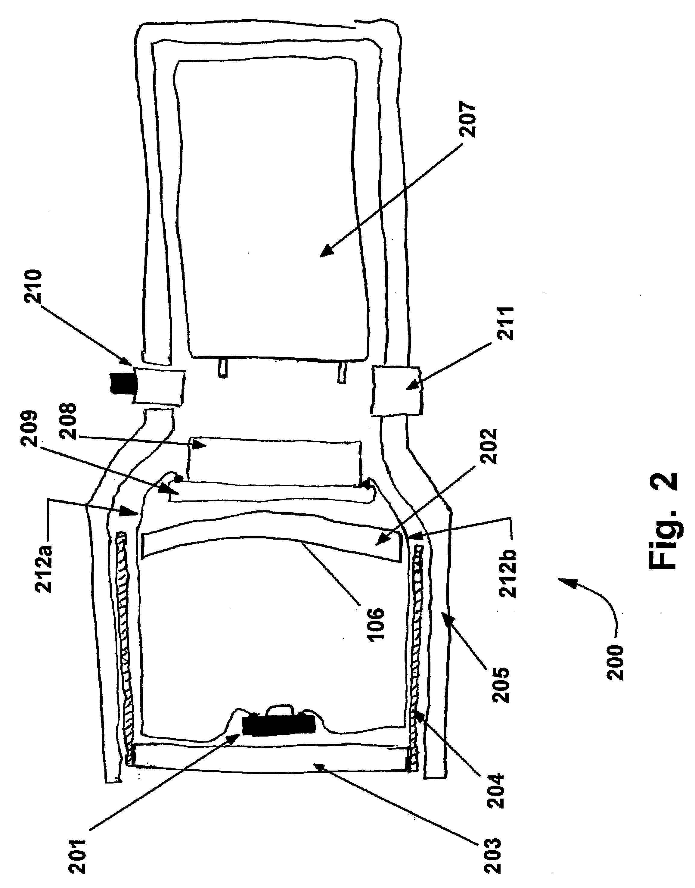
[0059] Referring to FIG. 2, the present invention 200 is an inspection lamp that resembles a flashlight. An LED 201 is provided as a source of radiation that is suitable for causing fluorescence of fluorescent materials. The LED is typically a high power type that typically requires heatsinking. The radiation from the LED may be mainly of wavelengths in a narrow spectral band that peaks in the range of 395 to 415 nanometers, so that the beam produced by the inspection lamp 200 is slightly visible but not so visible as to interfere with viewing of any fluorescent material that the inspection lamp 200 would be used to detect. Longer wavelengths will be found to be better for some purposes, but longer wavelengths would typically necessitate use of a viewing filter or viewing glasses that block at least most of the visible radiation produced by the LED 201. It is forseeable that in some applications it would be desirable to use a viewing filter that blocks at least some of the exciting ...

third embodiment

[0069] Referring to FIG. 4, the present invention is an inspection lamp 400 that resembles a flashlight and has lenses 402 to collimate the light from LEDs 401 into beams that merge together into a single beam. The inspection lamp 400 is similar to one described in U.S. patent application No. 20020093649, except the curved surfaces 403 of the lenses 401 are not spherical. The text and drawings of U.S. patent application No. 20020093649 is hereby incorporated by reference into this detailed description. The curved surfaces 403 may be ellipsoidal. The curved surfaces 403 may have a shape that is a mathematical combination of a paraboloid, an ellipsoid and a sphere. Other aspheric shapes of the curved surfaces 403 of the lenses 402 may be found to be useful. One shape that has been found to be useful is 58% paraboloidal and 42% spherical. This was found suitable if the radius of curvature of the central portions of the curved surfaces is 9.6 millimeters, the overall lens thickness is 4...

fourth embodiment

[0078] Referring to FIG. 5, the present invention is an inspection lamp 500 that has an LED 501 and a transparent optic 502 that uses reflection or both refraction and reflection to collimate the radiation from the LED 501 into a beam. The transparent optic 502 would typically resemble ones used in the Lumileds “Luxeon with Optics” high power LED light sources, but would typically be larger in order to produce a better beam. The transparent optics used by Lumileds are typically 20 millimeters in diameter, and a transparent optic 502 for the inspection lamp 501 would preferably be 25 to 50 millimeters in diameter.

[0079] Much of the radiation from the LED 501 hits the inner surface 503 of a hollow cylindrical region of the transparent optic 502, and as a result is refracted into a direction that is more perpendicular to the axis of the transparent optic 502. After this refraction, the radiation experiences total internal reflection by the rear surface 504 of the transparent optic 502....


PUM


Abstract

LED lamp has LEDs aimed rearwards with either a concave mirror to the rear of each LED, or one concave mirror to the rear of two or more LEDs, collecting the light from the LEDs to form a forward projecting beam. LEDs may be high power types that require heatsinking. LED lamp may have a lens forward of each LED to collimate the radiation produced by the LEDs into a beam, where at least one lens has at least one aspheric curved surface. LED lamp may have a transparent reflective optic to collimate the radiation produced by each LED into a beam. For an inspection lamp, the LEDs typically have a peak wavelength of 395 to 415 naometers for seeing the area being irradiated but not so visible as to overwhelm fluorescence of fluorescent materials to be detected. Other wavelengths may be used. LED inspection lamp has a combination of LEDs of different wavelengths or a combination of at least one LED and at least one other light source such that the lamp produces radiation suitable for detection of materials to be detected and adequately illuminates the area being irradiated. LED lamp has LEDs that produce a beam of suitable radiation with a width of 10 degrees or less without additional optics. LED inspection lamp has head attached to a flexible member, with head serving as heatsink for one or more high power LEDs. Current regulator circuits are also disclosed.

Description

CROSS-REFERENCE TO RELATED APPLICATIONS [0001] This application claims the benefit of the filing date of U.S. Provisional Patent Application No. 60 / 481,062 filed 7 Jul. 2003 under the title LED INSPECTION LAMP AND LED DRIVER CIRCUIT FOR USE IN THE SAME; U.S. Provisional Patent Application No. 60 / 481,986 filed 1 Feb. 2004 under the title LED INSPECTION LAMP AND DRIVER CIRCUITRY FOR THE SAME; and U.S. Provisional Patent Application No. 60 / 521,276 filed 24 Mar. 2004 under the title LED INSPECTION LAMPS AND LED DRIVER CIRCUITS FOR THE SAME. The content of the above Provisional Patent Applications is hereby expressly incorporated by reference into the detailed description of hereof.FIELD OF THE INVENTION [0002] This invention is related to the general field of LED lamps, and in particular to the structure and driving circuitry for such lamps, and to such lamps for inspection (non-destructive testing). BACKGROUND OF INVENTION [0003] LED lamps are known. For example, inspection lamps that ...

Claims


Application Information

Patent Timeline
IPC IPC(8): F21L4/00F21L4/02F21L4/06F21V23/04H05B33/12H05B33/22H05B37/00H05B44/00
CPCF21L4/005F21L4/027F21L4/06F21V7/0008F21V7/0075Y02B20/347F21Y2101/02G01N21/6447H05B33/0803H05B33/0818F21V23/0414F21Y2115/10F21Y2113/13Y02B20/30H05B45/38H05B45/32H05B45/34H05B45/395
Inventor KLIPSTEIN, DONALD J.BRASS, JACK
Owner ALLTEMP PROD CO LTD
Why Eureka
Try Eureka