Fan impeller for electrical machines

a technology of electrical machines and impellers, which is applied in the direction of machines/engines, portable power-driven tools, liquid fuel engines, etc., can solve the problems of unnecessarily high rate of fan drive, disturbing etc., to reduce the drive power, reduce the noise and improve the oscillatory behavior of the fan blades

Inactive Publication Date: 2005-01-13
SEG AUTOMOTIVE GERMANY GMBH
View PDF11 Cites 16 Cited by
  • Summary
  • Abstract
  • Description
  • Claims
  • Application Information

AI Technical Summary

Benefits of technology

[0004] With the present means of attaining the object of the invention, the aim is not only to reduce the drive power at the fan wheel at high rotational speeds, but also to markedly reduce the disturbing noises occurring there and to thereby simultaneously improve the oscillatory behavior of the fan blades.

Problems solved by technology

The quantity of cooling air conveyed creates disturbing sounds, particularly at higher rotational speeds.
Furthermore, additional power is required from the internal combustion engine of the motor vehicle to drive the fan wheel to convey the cooling air at an unnecessarily high rate in the upper speed range.
Since the inwardly directed, swivelable ends of the fan blades also extend freely into the air channels at high rotational speeds, the disturbing fan noise is further increased as a result.
In addition, blade oscillations occur there when the drive speed of the fan wheel fluctuates, the blade oscillations being capable of generating additional noises and resulting in material fatigue, in particular, and, therefore, to the fan blades breaking off.

Method used


Image

  • Fan impeller for electrical machines
  • Fan impeller for electrical machines

Examples


Embodiment Construction

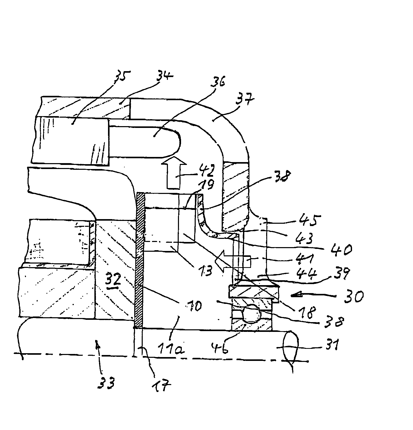
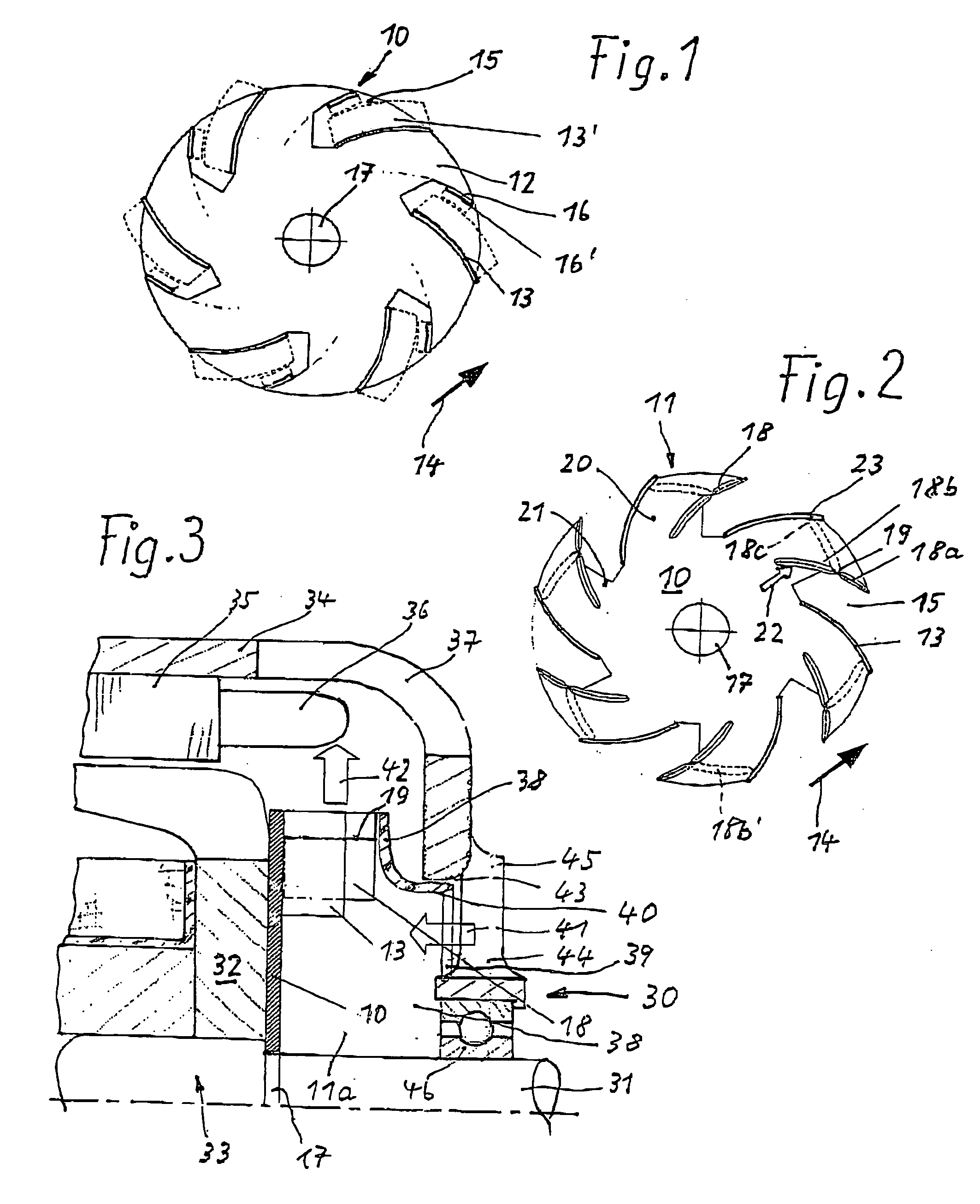
[0014]FIG. 1 shows the top view of a fan disk 10 for manufacturing a fan wheel 11 according to FIG. 2. Circular fan disk 10 is stamped out of a sheet metal plate 12 made of sheet steel, whereby it has a certain number of first fan blades 13 distributed around the circumference on its front, axially outwardly directed end face. Fan blades 13 are stamped out of the sheet steel of fan disk 10 and are bent outwardly axially frontward. Fan blades 13 are also tilted, from the inside to the outside in the radial direction, against the direction of rotation of fan wheel 10—indicated by an arrow 14—and are also bent backward. Before fan blades 13 are bent outwardly, they are located in the plane of fan disk 10, as indicated in FIG. 1 with dotted lines and labeled with reference numeral 13′. A stamped-out area 15 exists for each of these fan blades 13 on the circumference of fan disk 10. Each of these stamped-out areas 15 further includes a holding clip 16—that is also stamped out there out o...


PUM


Abstract

The present invention relates to a fan wheel (11) for electrical machines, in particular for alternators of motor vehicles, with a fan disk (10) that, on its axially outwardly directed end face, has a number of fan blades (13, 18) distributed around the circumference in the shape of a circular ring, the fan blades extending away from the fan disk in the axial direction, so that cooling air beneath the fan blades can be drawn in axially and blown radially outwardly between air channels (20, 21) formed between them. One part (18) of each of the fan blades is joined in a fixed manner with the fan disk (10) via only its radially outward end section (18a), so that each inner end section (18b) is swiveled radially increasingly outwardly by a centrifugal force (22) occurring there as rotational speeds increase, to reduce the cooling air stream.
To minimize not only the speed-dependent adaptation of the cooling air quantity to the cooling needs of the machine, but the flow noises as well, preferably only every second fan blade (18) is provided with an inner end section (18b) capable of being swiveled outwardly by centrifugal force (22), while the other, adjacent, first fan blades (13) are rigid along their entire length and are connected to the fan disk (10) in a fixed manner.

Description

BACKGROUND INFORMATION [0001] The present invention relates to a fan wheel for electrical machines, in particular alternators of motor vehicles, according to the general class of claim 1. [0002] Fan wheels are typically used to cool electrical machines, in particular alternators in motor vehicles, the fan wheels having rigid fan blades and being dimensioned such that they deliver enough cooling air, even at low rotational speeds, to dissipate the heat from power losses occurring in the electrical machine. In the case of fan wheels with rigid blades, the quantity of air conveyed increases as rotational speed increases. Since, starting at a certain rotational speed, the heat from power losses from generators in motor vehicles does not increase as drastically as it does in the lower rotational speed range, more air is conveyed by the fan wheel at higher rotational speeds that would be required to dissipate the heat from power losses. The quantity of cooling air conveyed creates disturb...

Claims


Application Information

Patent Timeline
Patent Type & Authority Applications(United States)
IPC IPC(8): F04D29/28F04D29/30H02K9/06
CPCF04D29/282H02K9/06F04D29/305B25F5/008
Inventor BRAUN, HORSTLUTZ, HANS-JOACHIM
Owner SEG AUTOMOTIVE GERMANY GMBH
Why Eureka
Try Eureka