Refrigeration device

a refrigeration device and refrigeration technology, applied in the direction of lighting and heating apparatus, electrical apparatus construction details, heating types, etc., can solve the problems of increasing interference noise, complicated wiring pattern, and easy to become complicated, and achieve the effect of reducing the size of the printed wiring board

Active Publication Date: 2016-11-10
DAIKIN IND LTD
View PDF1 Cites 8 Cited by
  • Summary
  • Abstract
  • Description
  • Claims
  • Application Information

AI Technical Summary

Benefits of technology

[0018]Because of this, here, the wiring pattern on the printed wiring board can be further kept from becoming complicated in the case of employing the interleave

Problems solved by technology

However, in a configuration that uses a refrigerant jacket to cooled elements, it is easy for the wiring pattern to become complicated because the cooled elements are placed concentrated in the position of the refrigerant jacket.
Moreover, in the case of employing a configuration where a reactor is connected via a harness like in the conventional refrigeration device described above, not only are the cooled elements placed concentrated in the position of the refrigera

Method used


Image

  • Refrigeration device
  • Refrigeration device
  • Refrigeration device

Examples


Embodiment Construction

[0026]An embodiment of an air conditioning device serving as a refrigeration device pertaining to the present invention, and example modifications thereof, will be described below on the basis of the drawings. It should be noted that the specific configurations of the refrigeration device pertaining to the present invention are not limited to those in the following embodiment and example modifications thereof, and can be changed to the extent that they do not depart from the spirit of the invention.

(1) Configuration of Refrigeration Device

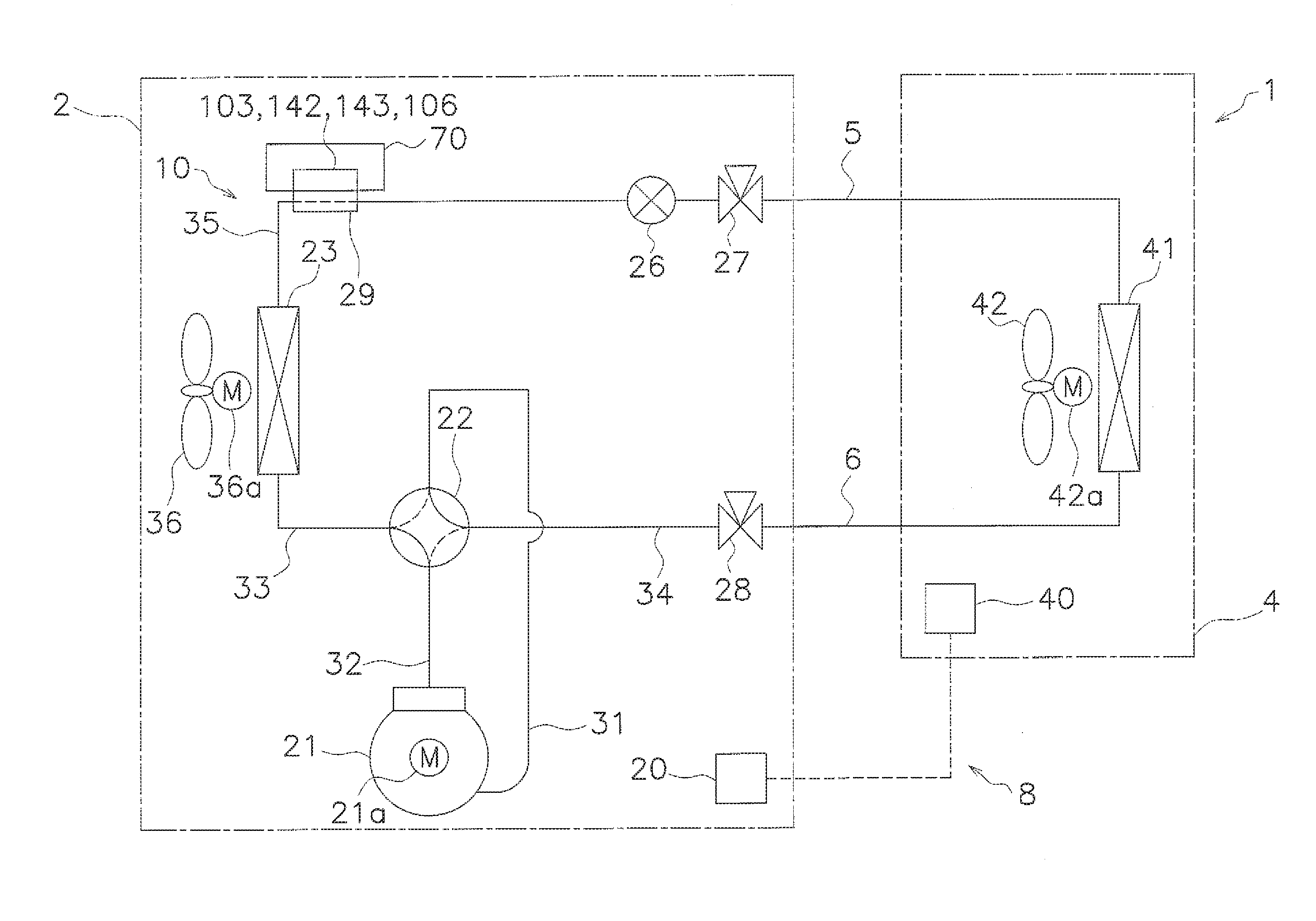
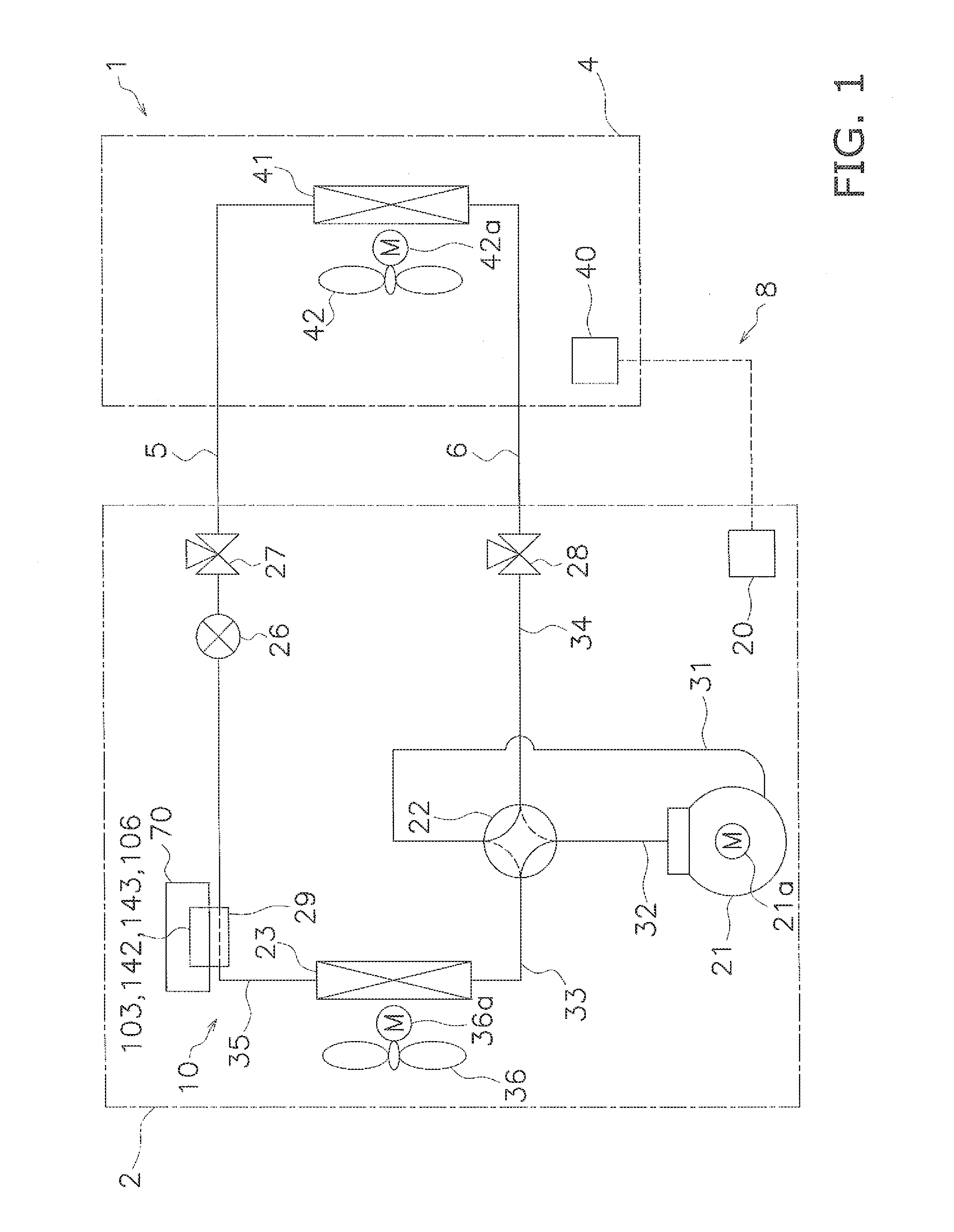
[0027]FIG. 1 is a schematic configuration diagram of an air conditioning device 1 serving as an embodiment of the refrigeration device pertaining to the present invention.

[0028]The air conditioning device 1 is a device that can cool and heat a room in a building, for example, by performing a vapor compression refrigeration cycle. The air conditioning device 1 is configured as a result of mainly an outdoor unit 2 and an indoor unit 4 being connected...


PUM


Abstract

A refrigeration device includes a high-voltage electrical parts group having reactors and cooled elements, a low-voltage electrical parts group, a printed wiring board with the electrical parts groups mounted, and a refrigerant jacket that uses refrigerant flowing through the refrigerant circuit to cool the cooled elements. The high-voltage electrical parts group form an interleaved power supply circuit. The cooled elements are placed in an order conforming to a power supply path of the power supply circuit. The power supply circuit has a rectifier circuit, a power factor improvement circuit, smoothing capacitors, and an inverter circuit. The power factor improvement circuit has the reactors connected to each other in parallel and diodes and switching elements serving as the cooled elements connected to each of the reactors. The reactors are placed on an opposite side of the smoothing capacitors, with the diodes and the switching elements sandwiched in between.

Description

TECHNICAL FIELD[0001]The present invention relates to a refrigeration device, and particularly a refrigeration device equipped with a refrigerant jacket that uses refrigerant flowing through a refrigerant circuit to cool cooled elements.BACKGROUND ART[0002]Conventionally, there has been a refrigeration device which, like the one described in patent document 1 (JP-A No. 2013-224785), is equipped with a refrigerant jacket that uses refrigerant flowing through a refrigerant circuit to cool cooled elements. In this refrigeration device, a high-voltage electrical parts group and a low-voltage electrical parts group are mounted on a main surface of a printed wiring board, and the refrigerant jacket is placed in such away that it can cool the cooled elements of the high-voltage electrical parts group. Furthermore, from the standpoint of simplifying the wiring pattern, a reactor is connected via a harness rather than being mounted on the main surface of the printed wiring board.SUMMARY OF I...

Claims


Application Information

Patent Timeline
IPC IPC(8): H05K7/20H02P27/06H02M1/42
CPCH05K7/20936H02P27/06H02M1/42F24F1/24F25B13/00F25B31/006F25B2313/0254F25B2400/077
Inventor FUJIWARA, MASAHIDEISHIZEKI, SHINICHIIKEDA, MOTONOBU
Owner DAIKIN IND LTD
Why Eureka
Try Eureka