
Wide temperature range chuck system

a chuck system and wide temperature range technology, applied in the direction of lighting and heating apparatus, instruments, furniture, etc., can solve the problems of reducing throughput and typical time-consuming, and achieve the effect of reducing throughpu

Inactive Publication Date: 2005-01-13
AXCELIS TECHNOLOGIES
View PDF10 Cites 20 Cited by
  • Summary
  • Abstract
  • Description
  • Claims
  • Application Information

AI Technical Summary

Benefits of technology

[0009] One method for achieving two temperature levels with a chuck is to use an electrical heat source to run high temperature processes and a liquid heat source to run low temperature processes. Such a system is disclosed, for example, in U.S. Pat. No. 6,461,801. However, in such systems the liqui

Problems solved by technology

This is typically time consuming and can decrease throughput.

Method used


Image

  • Wide temperature range chuck system
  • Wide temperature range chuck system
  • Wide temperature range chuck system

Examples


Embodiment Construction

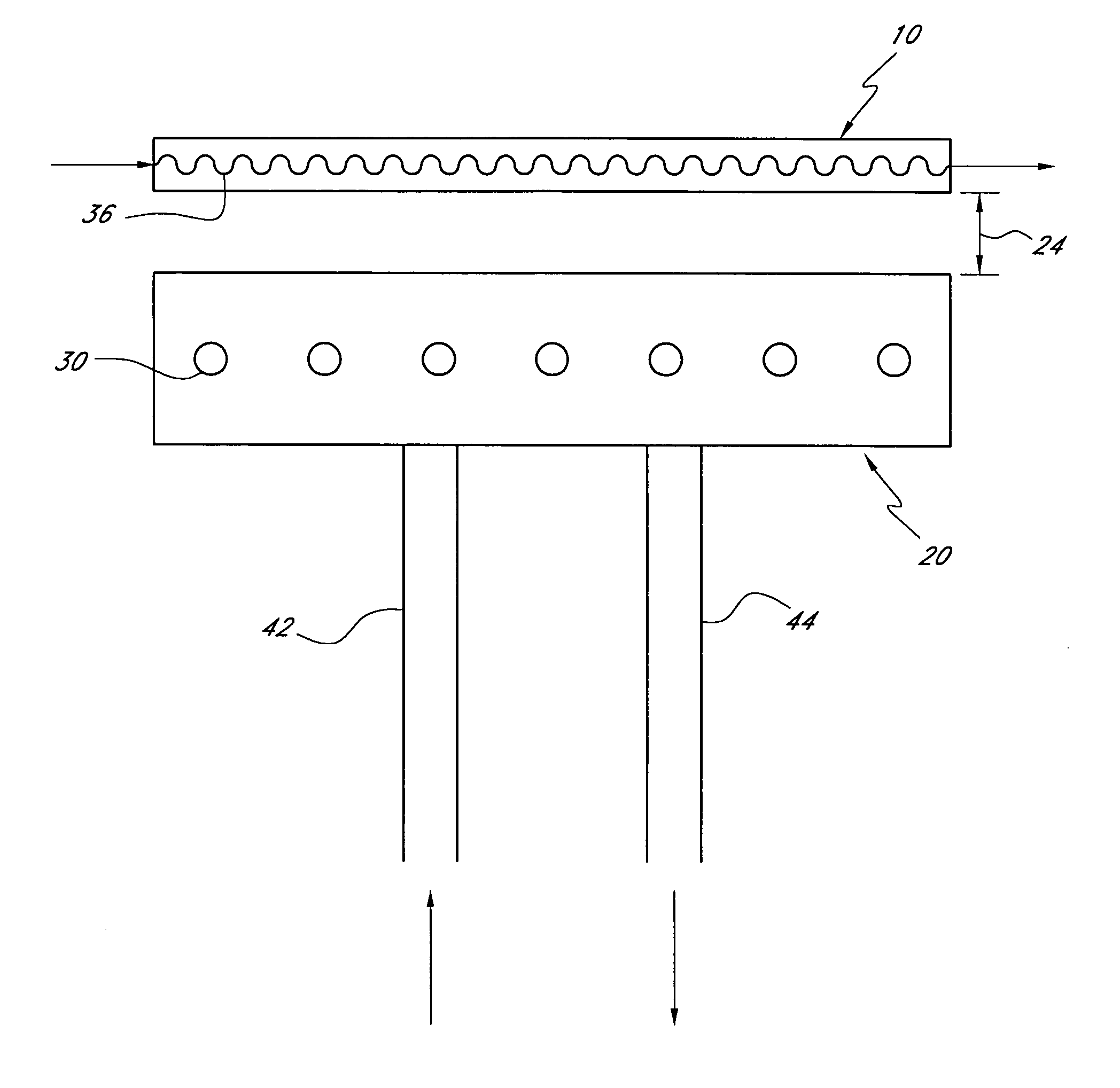
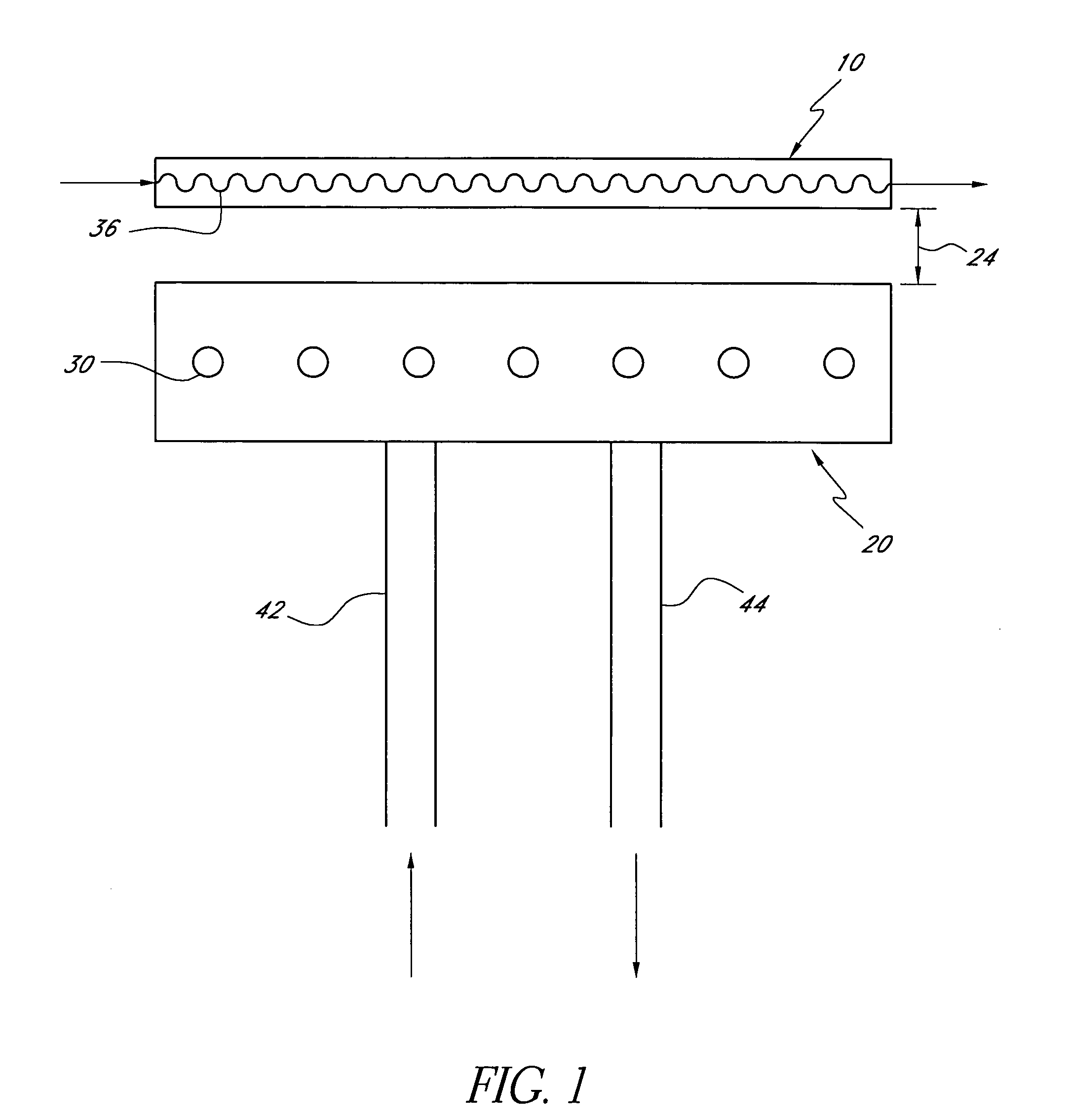
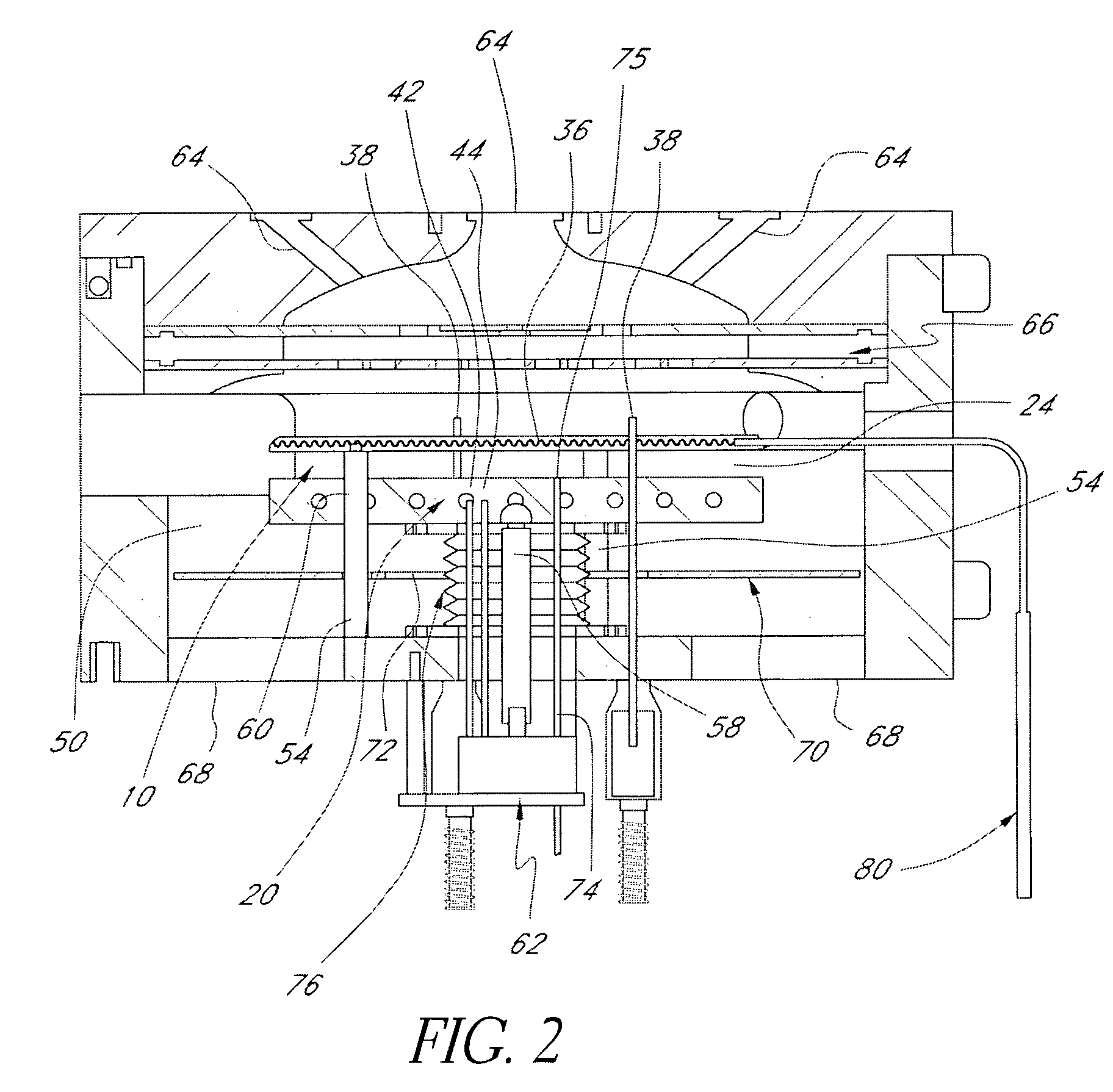
[0024] With reference to the attached figures, some preferred embodiments of a temperature-controlled apparatus for supporting a workpiece comprise a heat source configured to input heat to a workpiece support and a heat sink configured to remove heat from the support. In one embodiment, illustrated for example in FIG. 1, the heat source can be provided in a first chuck 10 upon which a workpiece can be supported, and the heat sink can be provided in a second chuck 20 positioned adjacent the first chuck 10.

[0025] In general, the first chuck (or “hot chuck”) 10 is configured to be actively heated and is configured to support a workpiece on its upper surface (or on support pins extending upwards therefrom). The second chuck (or “cold chuck”) 20 is generally maintained at a temperature below that of the first chuck 10 and is configured to remove heat from the hot chuck 10 through radiative, convective and / or conductive heat transfer. The rate of heat transfer between the hot chuck and ...


PUM


Abstract

An apparatus for supporting a workpiece in a process chamber is provided, comprising a first “hot” chuck having a surface for supporting the workpiece, the hot chuck including electrical heating elements for heating the hot chuck, and a second “cold” chuck having a fluid path formed therein for circulating a thermal transfer fluid. The cold chuck can be selectively moveable towards and away from the hot chuck to vary a rate of heat transfer between the hot chuck and the cold chuck.

Description

RELATED APPLICATIONS [0001] This application claims the benefit of U.S. Provisional Patent Application Ser. No. 60 / 469,050, filed on May 7, 2003.FIELD OF THE INVENTION [0002] The present invention relates generally to temperature control of workpiece support chucks for semiconductor processing equipment, and more particularly to rapid heating and cooling of such chucks. BACKGROUND OF THE INVENTION [0003] In many semiconductor processing steps, such as etching, deposition, annealing, etc., a workpiece (e.g., a silicon wafer, glass substrate, etc.) is supported within a processing chamber. Gaseous and / or plasma reactants are supplied to the surface of the workpiece while the workpiece is heated to specific temperatures. [0004] Typically, higher temperatures aid in achieving higher reaction rates, and therefore higher workpiece throughput. On the other hand, higher temperatures can sometimes cause damage to structures on partially fabricated integrated circuits. Additionally, certain c...

Claims


Application Information

Patent Timeline
IPC IPC(8): H01L21/00
CPCH01L21/67248H01L21/67109H01L21/00
Inventor WANG, ALBERT
Owner AXCELIS TECHNOLOGIES
Features
  • Generate Ideas
  • Intellectual Property
  • Life Sciences
  • Materials
  • Tech Scout
  • Unparalleled Data Quality
  • Higher Quality Content
  • 60% Fewer Hallucinations
Learn More