Iron golf club head

a golf club and iron technology, applied in the field of golf club heads, can solve the problems of aggravating the feeling of hitting, and achieve the effect of improving the vibration absorption characteristic at the time of hitting

Inactive Publication Date: 2005-01-13
BRIDGESTONE SPORTS
View PDF15 Cites 44 Cited by
  • Summary
  • Abstract
  • Description
  • Claims
  • Application Information

AI Technical Summary

Benefits of technology

[0017] A high specific gravity resin layer may be provided on the first face, or in a lower and rear portion of the recess. By providing this high specific gravity resin layer, the vibration absorption charact

Problems solved by technology

If there is such void, the irregular vibration occurs at the ti

Method used


Image

  • Iron golf club head
  • Iron golf club head
  • Iron golf club head

Examples


examples 1 and 2

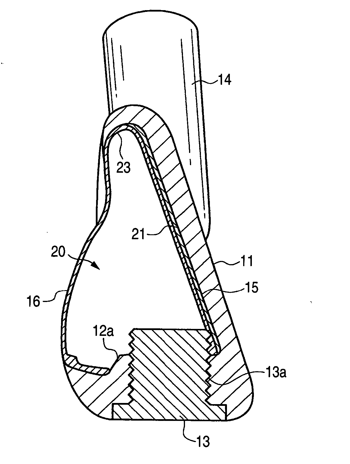
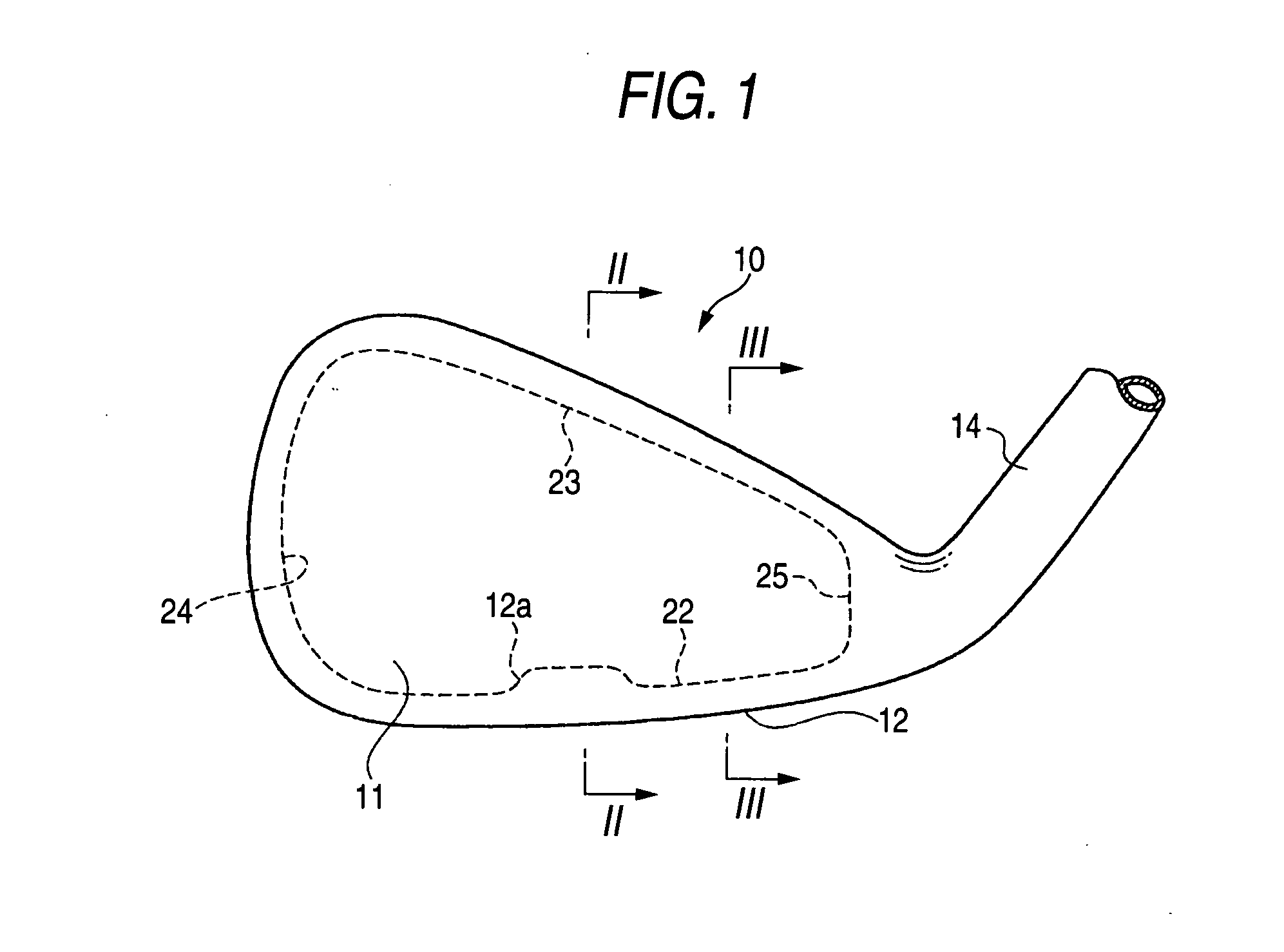
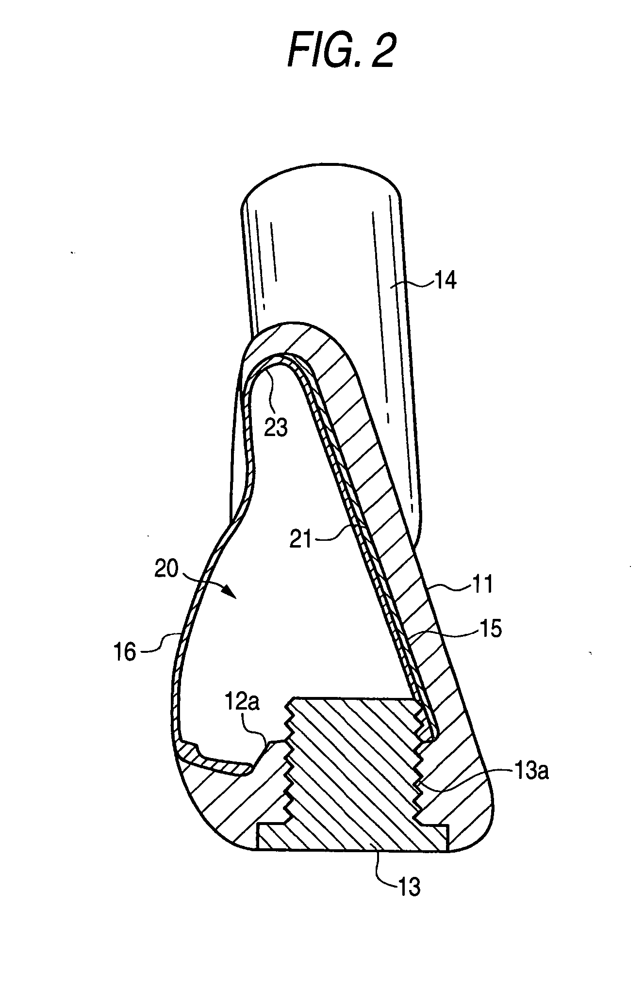
[0050] In the golf club head as shown in FIGS. 1 to 4, the radius of curvature of the crossing corner portion between the upper circumferential wall face 23 and the innermost face 21 was made to be 2 mm, and the radius of curvature of the crossing corner portion between the circumferential wall face 22 on the sole side and the innermost face 21 was made to be 50 mm or 70 mm. The FRP body 16 was a lamination of three layers, that is, two layers of UD prepreg using carbon fiber having an elastic modulus of 24 t / mm2 and one layer of cross prepreg using the came carbon fiber.

[0051] As a result, each golf club head had an excellent feeling of batting.

examples 3 and 4

[0052] The golf club head was fabricated with the same configuration as the examples 1 and 2, except that the high specific gravity resin layer 15 was omitted. These golf clubs provided a better feeling when hitting the ball.

example 5

[0053] The golf club head was fabricated with the same configuration as example 1, except that the ribs 30 were provided as shown in FIG. 5. The width of rib in the toe-heel direction was 2 mm, and the height from the innermost face 21 was 2 mm.

[0054] This golf club head had a quite excellent feeling of batting.


PUM


Abstract

An iron golf club head includes a head main body and an FRP body. The head main body includes a face portion, a first face along the face portion, second faces, and a recess behind the head portion. The second faces continue from a rear face of the face portion to the first face. The recess is defined by the first face and the second faces. The hollow FRP body is disposed in the recess, overlaps the first face and the second faces, and closes an opening portion of the recess. At least a part of crossing corner portions between the first face and the second faces has a curved face.

Description

BACKGROUND OF THE INVENTION [0001] 1. Field of the Invention [0002] The present invention relates to a golf club head for batting the golf ball, and particularly to an iron golf club head. More particularly, the invention relates to an iron golf club head including a head main body having a recess (cavity) opening at the rear face, and an FRP body provided in the recess. [0003] 2. Description of the Related Art [0004] Conventionally, the iron golf club heads were made of metal material alone such as stainless steel or cast iron. Recently, the iron golf club heads with an FRP (fiber reinforced plastic) material disposed behind the head main body have been available on the market. [0005] For example, JP-A-Sho.62-97570 discloses an iron club in which a CFRP (carbon fiber reinforced plastic) layer is attached on the back face of a hitting face to enhance the feeling of batting. [0006] Also, JP-A-Sho.63-19169 discloses that the CFRP layer is attached on the back face of the hitting face ...

Claims


Application Information

Patent Timeline
IPC IPC(8): A63B53/04A63B102/32
CPCA63B53/047A63B53/0475A63B59/0092A63B2053/0408A63B2053/0433A63B2053/045A63B2053/0454A63B2209/023A63B2053/0416A63B60/54A63B53/0408A63B53/0416A63B53/0433A63B53/045A63B53/0454
Inventor IMAMOTO, YASUNORIYAMAGISHI, HISASHI
Owner BRIDGESTONE SPORTS
Why Eureka
Try Eureka