Flow guiding structure for an internal combustion engine

a technology of flow guiding structure and internal combustion engine, which is applied in the direction of internal combustion piston engine, engine components, machines/engines, etc., can solve the problems of reduced effectiveness, high cost, and numerous drawbacks of catalytic converters

Inactive Publication Date: 2005-01-20
DOUCET REJEAN
View PDF7 Cites 63 Cited by
  • Summary
  • Abstract
  • Description
  • Claims
  • Application Information

AI Technical Summary

Benefits of technology

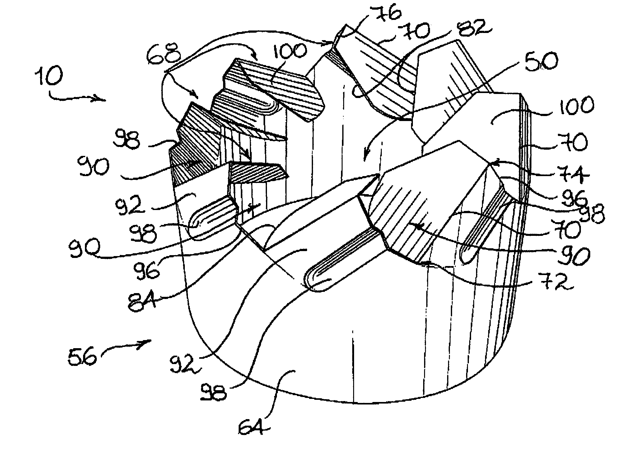
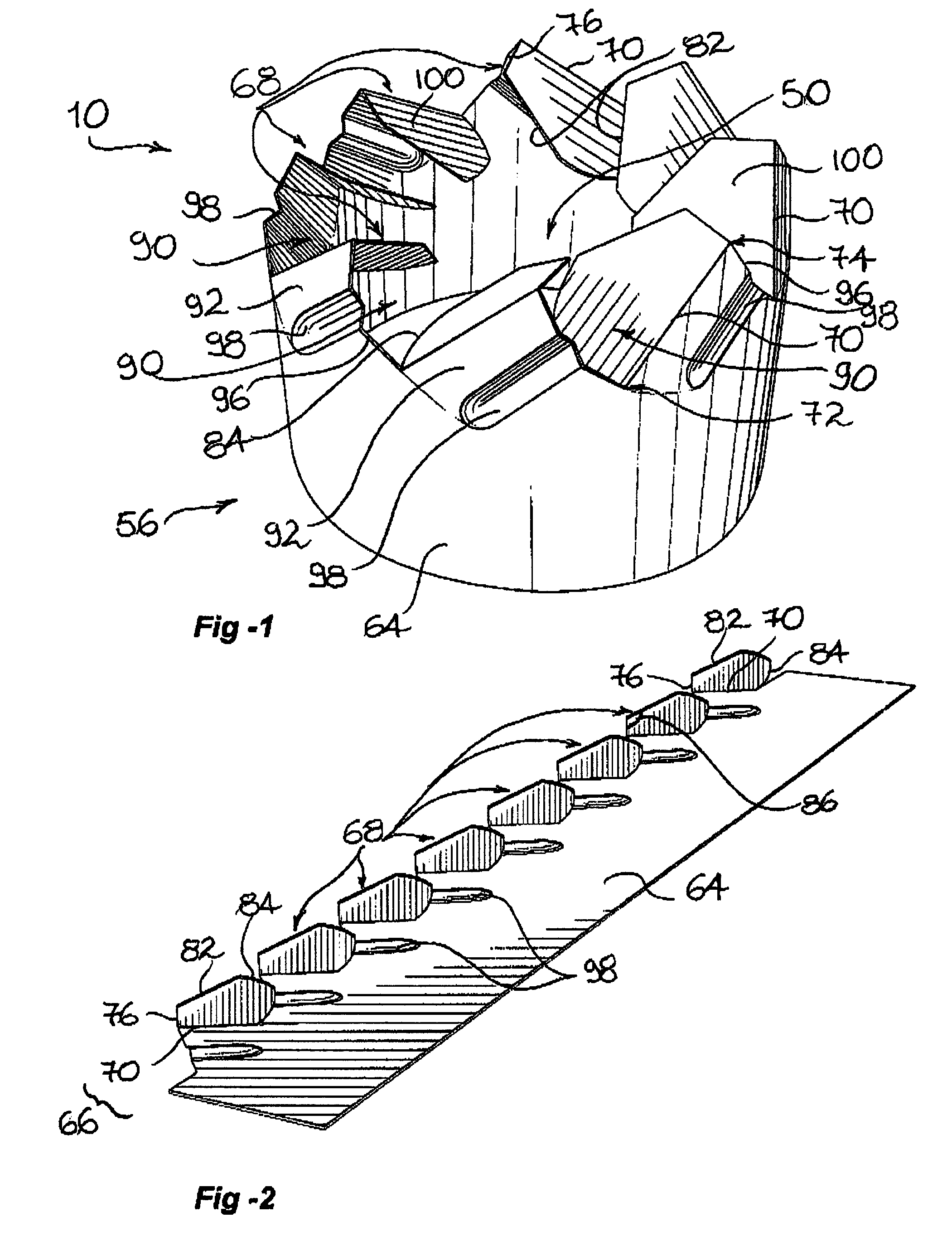
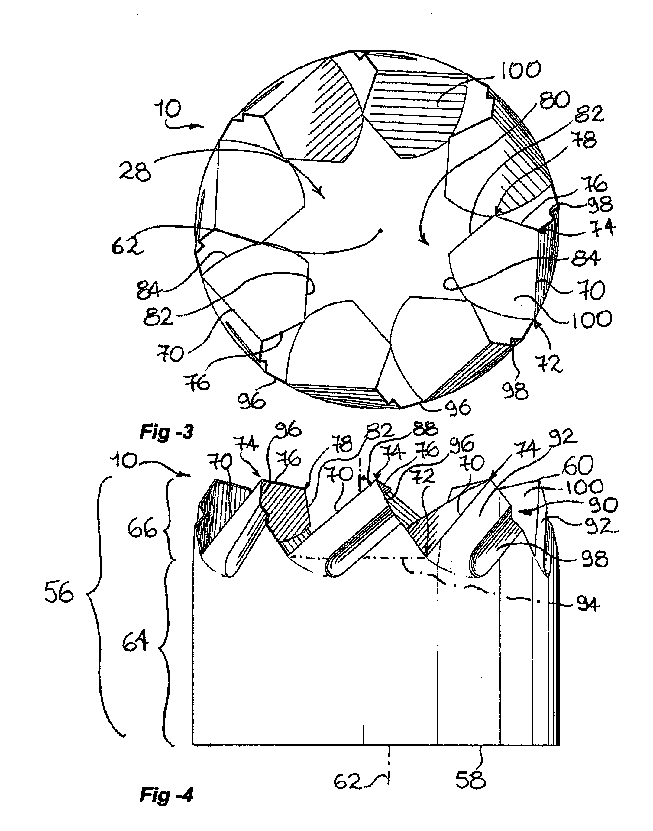
[0026] Advantages of the present invention include that the proposed structure allows for a flow of gas flowing into a gas passageway leading towards the combustion chamber of an internal combustion engine to be guided into a predetermined flow pattern so as to improve the mixing of air and fuel in the combustion chamber.
[0033] Optionally, the device allows for various types of swirl energy in the intake air based on characteristics of the engine and other vehicle parameters. For example, a general high swirling motion of the air is needed in the combustion chamber at lower engine operating speeds in order to enhance the fuel / air mixing process while a lower swirling motion of the air is desirable at higher engine speeds during which the swirl energy needed to assist in the mixing process is reduced due to the increased energy derived from the incoming gases at the higher piston speeds.

Problems solved by technology

However, it is presently understood that leaner fuel-air mixtures and improved mixing of fuel and air may tend to reduce the formation of nitrogen oxides.
Catalytic converters however suffer from numerous drawbacks.
For example, they are relatively costly and their effectiveness is reduced over time.
At present, carburetors manage to vaporise approximately 40% of the gasoline in the air and this slow vaporisation rate results in incomplete and inefficient combustion of the gasoline in the engine cylinders, resulting in relatively poor gasoline mileage for the vehicle being driven and relatively high output of combustion products or pollutants.
Although somewhat useful, such devices suffer from numerous drawbacks including that they are relatively expensive to manufacture and service.
Furthermore, they draw usable power from the engine and are prone to wear.
Still furthermore, they require space within the engine compartment for mounting and increase the overall weight of the motor vehicle.
Although somewhat useful, known prior art gas swirling devices suffer from numerous drawbacks.
Also, the proportion of the surface of the guiding vanes being used for effectively guiding the flow of gas is often considered to be too small.
Furthermore, some prior art devices suffer from the particular defect of overcomplexity, with resulting high manufacturing costs and a propensity to require service and / or repair.
Some prior art devices also create an undue restriction to the flow of gases.

Method used


Image

  • Flow guiding structure for an internal combustion engine
  • Flow guiding structure for an internal combustion engine
  • Flow guiding structure for an internal combustion engine

Examples


Embodiment Construction

[0042] Referring to FIGS. 5 and 7, there is shown a flow guiding structure in accordance with an embodiment of the present invention generally indicated by the reference numeral 10. The structure 10 is shown mounted in the air intake system of an internal combustion engine employing respectively a carburettor 12 and a fuel injector (not shown). It should be understood that although the structure 10 is shown being used with specific types of engines, the structured 10 could be used with any other suitable type of engines without departing from the scope of the present invention, as long as the air intake system of the engine includes a gas passageway leading towards a combustion chamber.

[0043]FIG. 5 illustrates, by way of example, the typical configuration of an air intake system for an internal combustion engine (not shown) of the type that employs a carburettor 12. The air intake system typically includes a gas passageway in the form of an air entry chamber 14 commonly referred to...


PUM


Abstract

A flow guiding structure for guiding into a clockwise swirling flow pattern gas flowing into a gas passageway leading toward a combustion chamber of an internal combustion engine. The structure includes a tubular peripheral wall having a base section for securing the structure to the gas passageway and an integrally extending guiding section. A plurality of guiding vanes extend radially inward from the guiding section each about a corresponding vane first edge. Each guiding vane includes a vane second edge extending in a geometrical plane perpendicular to the structure longitudinal axis. Each guiding vane further includes a substantially convex vane third edge. The guiding section is provided with a plurality of guiding bents formed therein and extending radially inwardly. The guiding bents are adapted to act as an auxiliary guide and as reinforcement for the structure.

Description

FIELD OF THE INVENTION [0001] The present invention relates to the general field of internal combustion engine accessories and is particularly concerned with a flow guiding structure for guiding into a predetermined flow pattern a volume of gas flowing into a gas passageway leading towards a combustion chamber of an internal combustion engine. BACKGROUND OF THE INVENTION [0002] As is well known in the art, internal combustion engines produce mechanical power from the chemical energy stored in hydrocarbon fuel. This energy is released by oxidising or burning fuel within the cylinders of the engine. [0003] The amount of power released from the fuel is function of the degree of oxidation and, hence, is dependent on the amount of oxygen available during combustion. As a general principle, the greater the degree of oxidation of the fuel, the higher the efficiency and the greater the power output, reflected respectively by the gas mileage and horsepower of a vehicle. [0004] Three major po...

Claims


Application Information

Patent Timeline
Patent Type & Authority Applications(United States)
IPC IPC(8): F02M29/06
CPCY02T10/146F02M29/06Y02T10/12
Inventor DOUCET, REJEAN
Owner DOUCET REJEAN
Why Eureka
Try Eureka