
Fluid delivery system for a flow cytometer

a flow cytometer and flow cytometer technology, applied in the direction of instruments, packaging, transportation and packaging, etc., can solve the problems of adversely affecting the results of a study, contaminating the sample fluid, and altering the character of the cells being examined, etc., to achieve easy and secure coupling, easy fitting, and easy uncoupling

Inactive Publication Date: 2005-01-20
STOWERS INST FOR MEDICAL RES
View PDF19 Cites 96 Cited by
  • Summary
  • Abstract
  • Description
  • Claims
  • Application Information

AI Technical Summary

Benefits of technology

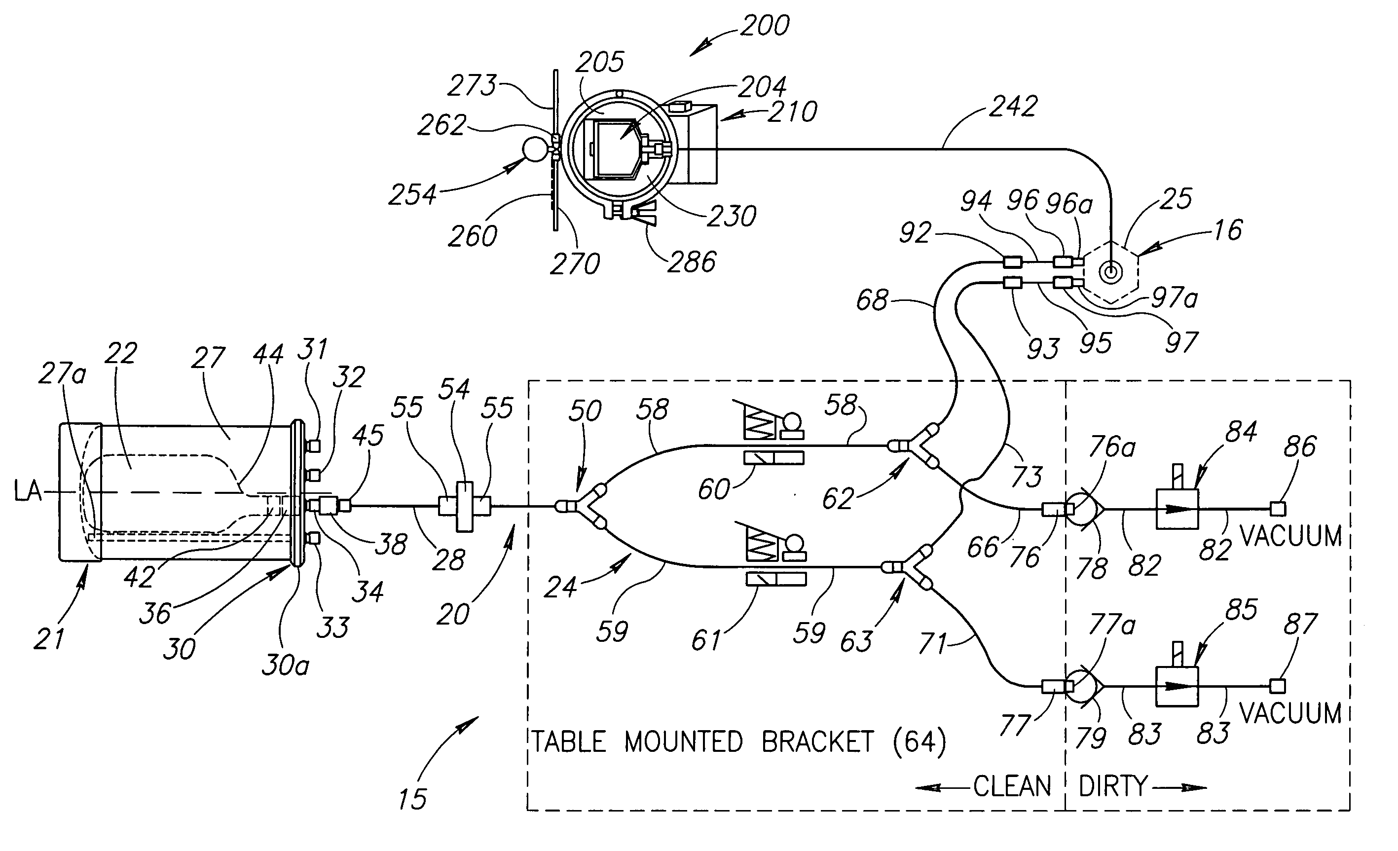
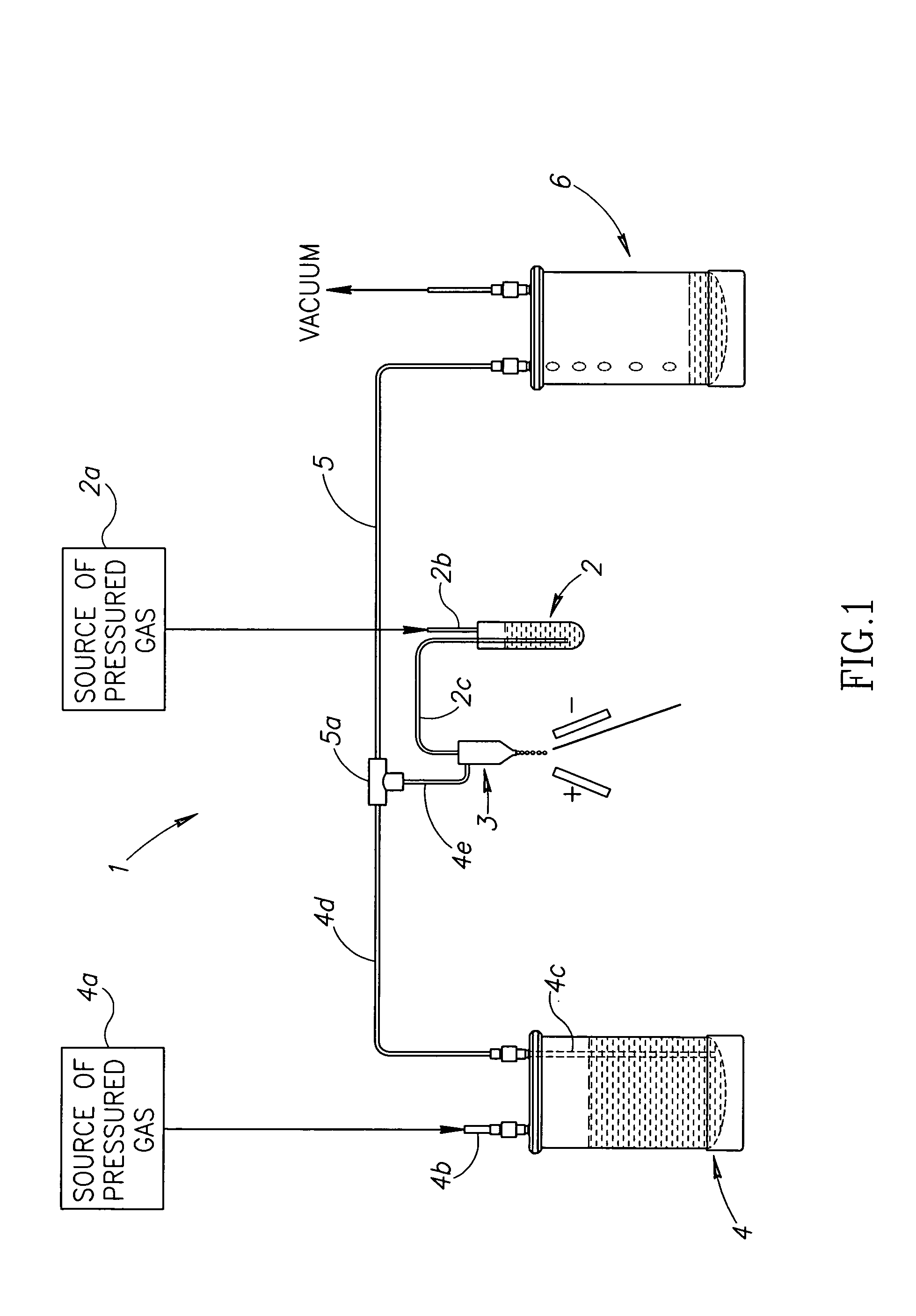
[0015] The tubing system, upon its connection to a FACS sorter, is closed to the ambient environment. The tubing system may be unitary in structure, formed of molded components, to be a single piece. The tubing system facilitates sheath fluid transported from a source to a flow cytometer, whereby air bubbles are inhibited from forming in the system. The system is sterile, thereby eliminating the need for bacteria removal filters along fluid lines (tubes), due to the system being sterile and closed to the ambient environment. This system also eliminates the need for in-line valves along the system. The tubing system can include one or a plurality of tube members. The multiple tube members are used to remove gas from the lines. Also, the sheath and sample fluids are in bags that maintain sterility and where gas is not commingled.
[0016] The sheath fluid is transferred to the flow nozzle of the flow cytometer by the tubing system. Fluid is transported through the system without any in-line valves or in-line flow control devices. The tubing system is typically transparent or translucent, allowing the user to see the fluid flow therein and detect any turbulence, air bubbles, or other conditions within the system that destroy the stability of aerosol formation after the fluid exits the flow nozzle. By viewing the flow, the user has visual knowledge of changes in the flow and can control it instantaneously.
[0018] The tubing system or set, through which the sheath fluid is transported, is universal and can be fitted to a variety of flow cytometers without significant modifications. It is designed to couple with a fluid source, an analytic device, and a waste system, and provide a sterile environment for the fluid. The tubing set is such that it couples easily and securely with a fluid source, analytic device, for example, a flow cytometer, and a waste system. The tubing set is also such that it uncouples easily with the aforementioned components. Additionally, the tubing set can be fit into prearranged configurations, such as table mounts and preconfigured waste systems. The tubing system is universal in that it can easily be fitted, placed onto, and removed from numerous flow cytometers without significant modifications. It also provides a path for the fluid that is closed to the ambient environment.
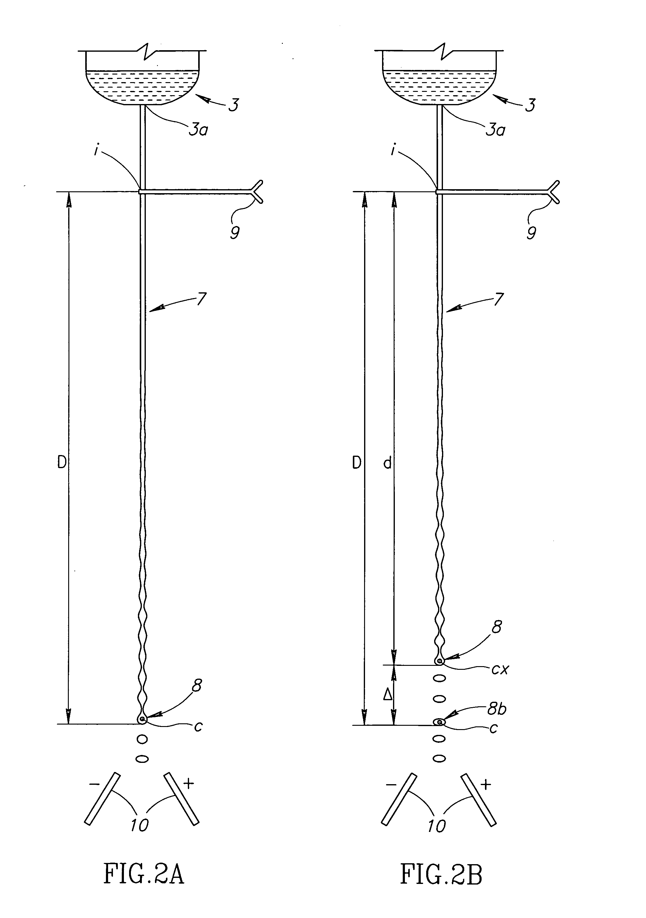
[0019] The present invention provides a sheath fluid delivery system that eliminates changes and fluctuations, typically decreases, in hydrostatic pressure at the flow nozzle of a flow cytometer. The present invention provides a tank that releases sheath fluid at a constant height, to travel a constant distance to the flow nozzle, to maintain constant hydrostatic pressure at the flow nozzle. This allows aerosol formation to be constant, resulting in highly stable FACS sorts.

Problems solved by technology

But if particles in the sheath fluid are smaller than the pore size, they pass through the filter and contaminate the sample fluid at the flow nozzle.
This is problematic because the character of the cells being examined can be altered.
Sheath fluid contaminated by microorganisms, microparticles, or nucleases, adversely impact the results of a study.
More importantly, if stem cells are sorted for therapeutic uses, the cells are unavailable for use if contaminated.
A common cause of contaminants in the sheath or sample fluid results from the introduction of contaminants by pressurized gas physically contacting the sheath or sample fluid.
The filters remove bacteria of a particular size, but are ineffective should bacteria or other contaminates pass beyond the filters.
Additionally, the tubes used for transporting the sheath or sample fluid may not have been sterilized.
Not only does the gas contain contaminants, but the gas typically diffuses into the sheath and sample fluid, affecting the purity of these fluids.
These washing procedures are elaborate, time consuming, and labor intensive.
Also, some components, such as the filter, are not cleansed because exposure to detergents destroys the filter.
Accordingly, such a system is not certifiably clean.
Hardware components directly contacting the sample and other components carrying fluids, which contact the sample, are not easily replaced or autoclaveable.
The current flow cytometry technology cannot be used for clinical sorting applications because the fluidic system is not designed for this intent.
Further, the contemporary tubing systems are not easily replaced with new sterile components.
The contemporary systems also experience changes in hydrostatic, or head, pressure, causing instability of stable aerosol formation.

Method used


Image

  • Fluid delivery system for a flow cytometer
  • Fluid delivery system for a flow cytometer
  • Fluid delivery system for a flow cytometer

Examples


example 1

[0086] A sheath tank, a stainless steel cylindrical tank with an approximately 8 inch diameter, a depth of at least 13⅜ inches, and able to withstand pressures of up to 100 psi when capped, was modified with an internal cylindrical tube (straw) that extended approximately 13 inches into the tank, to a point just above the floor. The tank was filled with approximately 8 liters of Dulbecco's Phosphate Buffered Saline (PBS). The cap had connections for pressure in, fluid out, and a pressure gauge. The pressure gauge included a differential pressure measuring (DPM) unit, that attached between the pressure in and fluid out connections. The differential pressure gauge measured the difference between gas pressure at the top of the tank and pressure of the fluid as it leaves the tank. The resultant readings are shown in FIG. 11A in a diagram of differential pressure (in pounds per square inch (psi) versus time (in minutes)).

[0087] The tank was sealed with the cap, so as to be air and water...

example 2

[0093] The tank of Example 1 was used, with the internal cylindrical tube removed, and a 5 liter bag of Dulbecco's PBS was placed into the interior of the tank. A Plexiglas board was also placed into the tank. The bag, at a line extending from the bag, was attached to the fluid out port, this fluid out port being the port that formerly accommodated the internal cylindrical tube (straw). This port also included a quick connect on the outside of the tank cover. The cap was sealed on the body of the tank, such that the tank was air and water-tight.

[0094] The tank was connected to the tubing set 24 as detailed above for Example 1. The tank was tilted to a horizontal position, where the bag rested on the Plexiglas board and the line that extended from the bag was also supported by this Plexiglas board. The tank was oriented so that the fluid out port, that accommodated the line that extended from the bag, was at a six-o'clock position. The tank was pressurized to approximately 60 psi us...


PUM

PropertyMeasurementUnit
pressuresaaaaaaaaaa
pore sizeaaaaaaaaaa
heightaaaaaaaaaa

Abstract

Systems for sheath fluid and sample fluid transport from containers to an analytic device, such as a flow (cell) cytometer, are disclosed. These systems are sterile and remain so, as they are closed to the ambient environment. As a result, fluids of high purity reach the analytic device, and in the case of a flow cytometer, the desired cells are sorted in sort of high purity.

Description

CROSS-REFERENCES TO RELATED APPLICATIONS [0001] This application is related to and claims priority from commonly owned U.S. Provisional Patent Applications: Ser. No. 60 / 476,380, filed Jun. 6, 2003, entitled: TUBING SYSTEM FOR USE WITH A CELL CYTOMETER, Ser. No. 60 / 504,105, filed Sep. 19, 2003, entitled: SHEATH DELIVERY SYSTEM, and Ser. No. 60 / 526,747, filed Dec. 3, 2003, entitled: SAMPLE FLUID DELIVERY SYSTEM, all three of these U.S. Provisional Patent Applications are incorporated by reference herein.FIELD OF INVENTION [0002] The present invention relates to systems, apparatuses, and methods, for use in sorting cells, whereby the inventions are used with any of a variety of flow cytometers. In particular, the present invention is directed to sterile systems for supplying and delivering sheath and sample fluid to the flow nozzle of a flow cytometer. BACKGROUND OF INVENTION [0003] Flow cytometry is a technology that utilizes an instrument in which particles, such as cells, in suspens...

Claims


Application Information

Patent Timeline
Patent Type & Authority Applications(United States)
IPC IPC(8): G01N15/14
CPCG01N15/1404G01N2015/149G01N2015/1409G01N15/1409G01N15/149
Inventor HAUG, JEFFREY S.
Owner STOWERS INST FOR MEDICAL RES
Learn More