Device for cooling and electrical machine, in particular a synchronous electrical machine having permanent magnets

a technology of electrical machines and electrical components, which is applied in the direction of magnetoelectric circuits, vessel construction, marine propulsion, etc., can solve the problems of reducing the residual induction of the residual induction, affecting the operation and maintenance of the machine, and a large majority of electrical losses

Inactive Publication Date: 2005-01-20
JEUMONT ELECTRIC
View PDF5 Cites 44 Cited by
  • Summary
  • Abstract
  • Description
  • Claims
  • Application Information

AI Technical Summary

Benefits of technology

The object of the invention is to propose a device for cooling an electrical machine comprising a stator in which successive recesses are provided in a circumferential direction of the stator about a stator axis, which recesses each contain at least one winding and open out on an inlet face of the stator, and a rotor mounted rotatably about the axis of the stator and having an active face which is located facing the inlet face of the stator, while forming a free space or an air gap with the inlet face of the stator, and on which are located magnetic elements constituted preferably by permanent magnets, each of the recesses of the stator extending in a longitudinal direction and from the inlet face of the stator, which face is directed towards the air gap, in a direction perpendicular to the longitudinal direction, in accordance with a specific depth of the recess, the cooling device comprising, in each of the stator recesses, at least one cooling tube extending in the longitudinal direction of the recess and means for setting in circulation a cooling fluid inside each of the cooling tubes of the stator, the cooling tubes being in communication at their ends with manifolds for the supply and evacuation of cooling fluid which are connected to a cooling circuit comprising at least one pump and one heat exchanger, so that the cooling fluid circulates in a closed circuit, this cooling device permitting a substantial improvement in the thermal protection of the magnetic rotor elements constituted preferably by permanent magnets.

Problems solved by technology

The electrical losses which occur inside some elements of electrical machines give rise to heating which may be detrimental to the functioning and the maintenance of the integrity of the machine.
In particular, in the case of synchronous machines having permanent magnets, a very large majority of the electrical losses are produced in the windings and the magnetic circuit of the stator.
Excessive heating of the permanent magnets results in a reduction in their residual induction and in a reduction in the performance of the electrical machine.
However, that arrangement is not the most favourable, in particular in the case of synchronous machines having permanent magnets, inasmuch as the cooling tubes cannot protect the permanent magnets against heating by the windings at the location of the inlet portion of the recesses which is directed towards the air gap.
Those disadvantages exist both in the case of radial flux machines in which the rotor is mounted inside an annular stator in a coaxial arrangement and in the case of discoidal machines in which the stator and the rotor each comprise at least one disc carrying magnetic elements on one or two active faces, the active faces of the stator and rotor discs being placed opposite one another, while providing an air gap, so that axial flux circulation is obtained, that is to say, in accordance with the direction of the axis common to the rotor and stator discs.

Method used


Image

  • Device for cooling and electrical machine, in particular a synchronous electrical machine having permanent magnets
  • Device for cooling and electrical machine, in particular a synchronous electrical machine having permanent magnets
  • Device for cooling and electrical machine, in particular a synchronous electrical machine having permanent magnets

Examples


Embodiment Construction

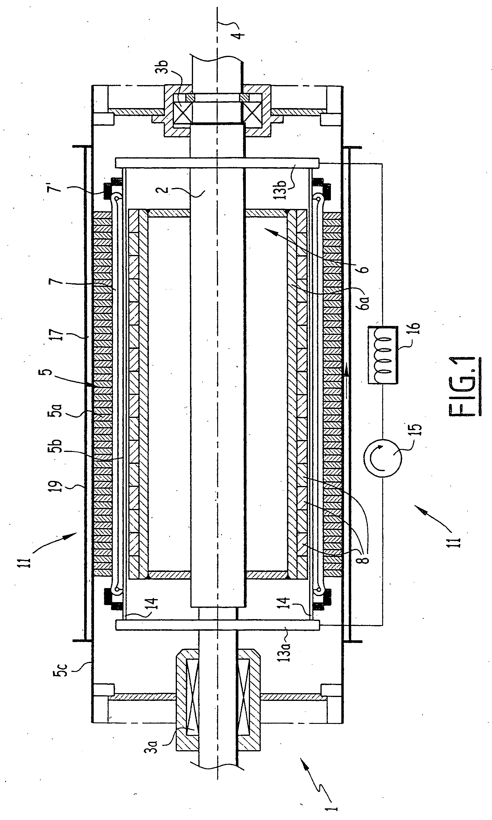
FIG. 1 shows the whole of a radial flux machine and of a device for cooling the stator of the machine.

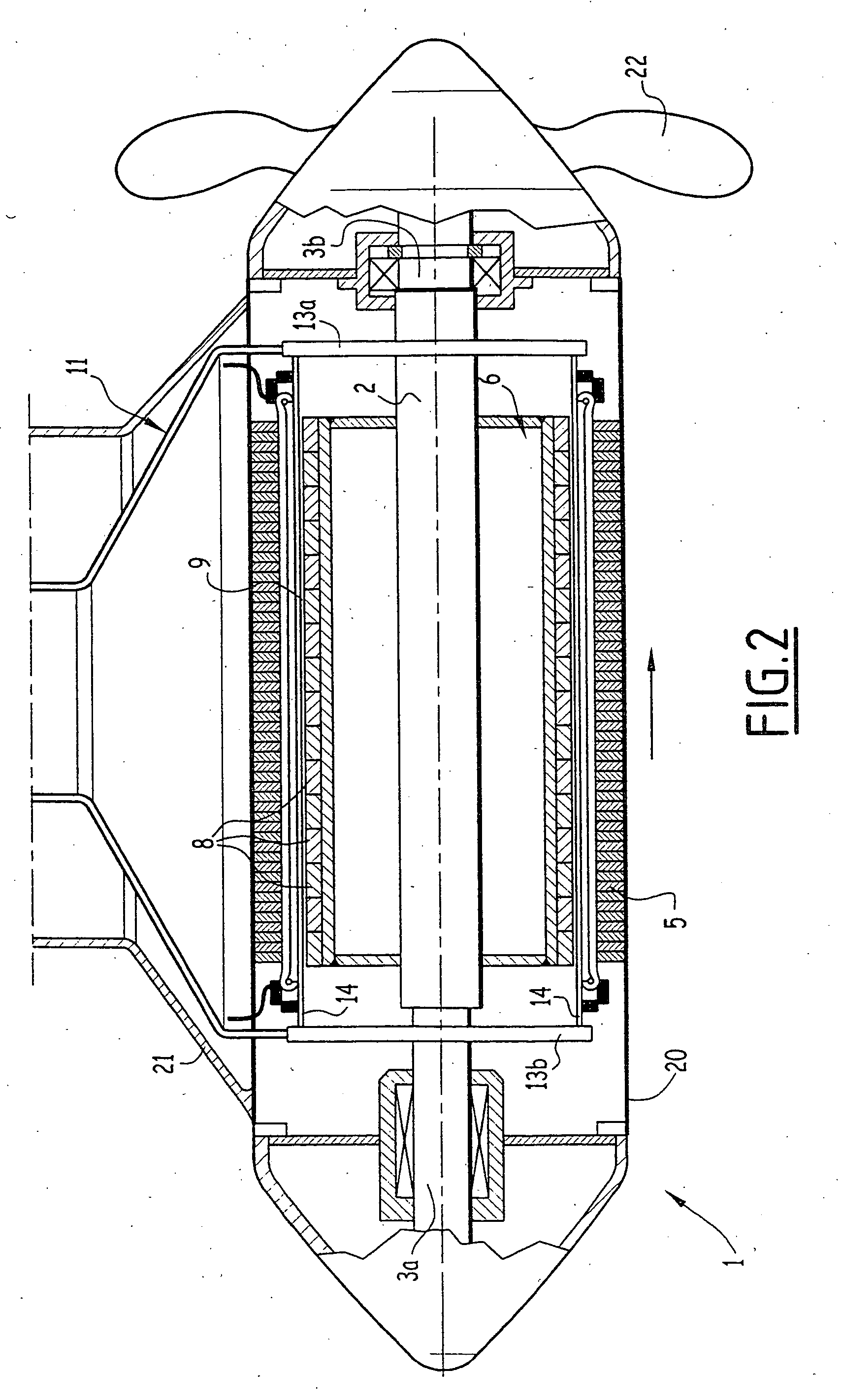
The radial flux machine, generally indicated by the reference sign 1, comprises a longitudinal shaft 2 mounted rotatably about an axis 4 inside bearings 3a and 3b.

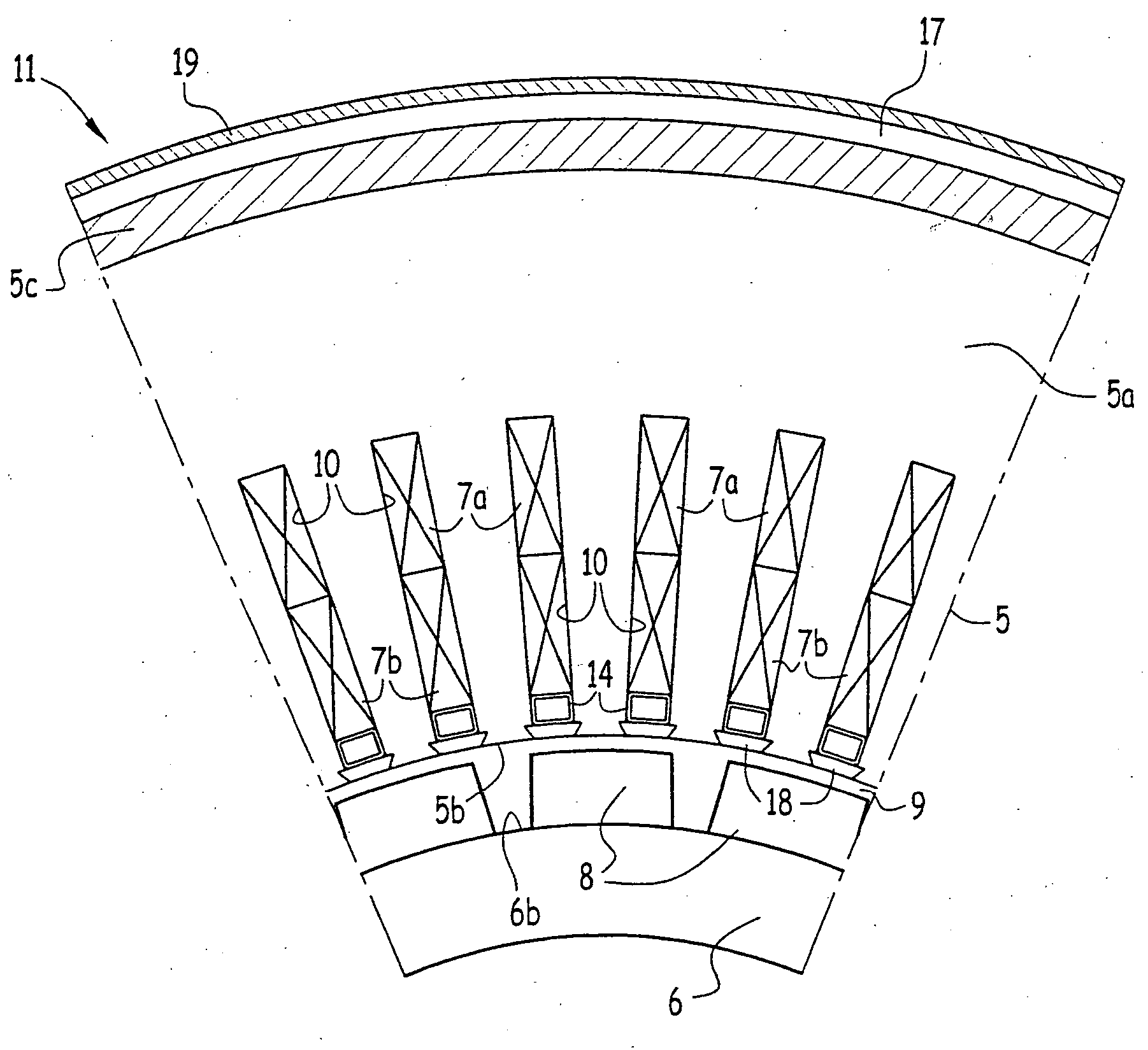
Fastened to the shaft 2 is the rotor 6 of the electrical machine whose annular stator 5 surrounds the rotor over its entire external periphery.

The stator 5 comprises a magnetic circuit 5a which may be constituted, at least partially, by a stack or roll of pieces of magnetic sheet-metal. Recesses extending along the entire length of the stator in the axial direction 4 and to a specific depth in the radial direction are provided inside the magnetic circuit 5a of the stator. The recesses are placed in succession over the circumference of the internal periphery of the stator, about the axis 4 which constitutes both the axis of the rotor and the axis of the stator.

At least one electrical winding 7 which is connected by e...


PUM


Abstract

The cooling device according to the invention comprises, in each of the stator recesses which contain windings, a cooling tube located in the longitudinal direction of the recess and supplied with cooling fluid. The cooling tube is located in the inlet portion of each of the recesses which is closest to the air gap, and thus constitutes a thermal barrier between the windings of the stator and the permanent magnets carried by the rotor. A device for the external cooling of the stator may be combined with the tubes for cooling the internal portion of the stator.

Description

TECHNICAL FIELD The invention relates to a device for cooling an electrical machine and in particular a synchronous electrical machine having permanent magnets. BACKGROUND TO THE INVENTION Electrical machines such as motors or alternators generally comprise a stator having a magnetic circuit in which are provided recesses which are to receive windings and which are distributed in a circumferential direction about the axis of the stator, and a rotor which is mounted rotatably about the axis of the stator and which comprises an active surface to which magnetic elements constituted by permanent magnets are secured, in the case of synchronous electrical machines having permanent magnets. The recesses of the stator extend in a longitudinal direction and to a specific depth, in the magnetic circuit of the stator, in a direction perpendicular to their longitudinal direction, and they open out on an inlet face of the stator, which face is located facing the active surface of the rotor co...

Claims


Application Information

Patent Timeline
Patent Type & Authority Applications(United States)
IPC IPC(8): H02K1/20H02K3/24H02K9/00H02K9/19H02K9/20H02K21/24
CPCB63H5/125B63H2005/1254H02K21/24H02K9/19H02K3/24B63H23/24B63H5/07B63H21/383B63H2005/075Y02T70/50H02K9/197
Inventor PHILIPPART, OLIVIER
Owner JEUMONT ELECTRIC
Why Eureka
Try Eureka