Moisture-proof device for motor

Inactive Publication Date: 2005-01-20
DELTA ELECTRONICS INC
12 Cites 23 Cited by

AI-Extracted Technical Summary

Problems solved by technology

However, due to the fact that this kind of motor is placed in the bathroom or in the toilet, it is easy to get wet all the time.
Thus, the moisture-proof design for this kind of motor is an un...

Method used

[0028] As shown in FIG. 4, the moisture-proof device of the present invention is covered on the stator of the motor. The assembly of the moisture-proof device and the stator can be bonded together via an adhesive. Specifically, the first covering part 221 is shaped as an annular plate, and the second covering part 222 is shaped as a cylinder. Due to the required amount of the adhesive for the present invention is much less than that of the prior art, it will save a lot of the baking time of the process. Therefore, the present invention will l...

Benefits of technology

[0009] It is therefore an object of the present invention to propose a moisture-proof device for the motor to be provided with a good moisture-proof effect, It is t...

Abstract

A moisture-proof device is provided to be used in a fan having a stator for isolating the stator from moisture. The moisture-proof device includes a first covering part for covering a circuit board of the stator of the motor, and a second covering part connected to the first covering part for covering a coil and a core of the stator of the motor, thereby isolating the stator of the motor from moisture, wherein the first covering part and the second covering part are integrally formed as a single piece, wherein the moisture-proof device is disposed in a hub of the fan.

Application Domain

Technology Topic

Image

  • Moisture-proof device for motor
  • Moisture-proof device for motor
  • Moisture-proof device for motor

Examples

  • Experimental program(1)

Example

[0026] The present invention will now be described more specifically with reference to the following embodiments. It is to be noted that the following descriptions of preferred embodiments of this invention are presented herein for purpose of illustration and description only; it is not intended to be exhaustive or to be limited to the precise form disclosed.
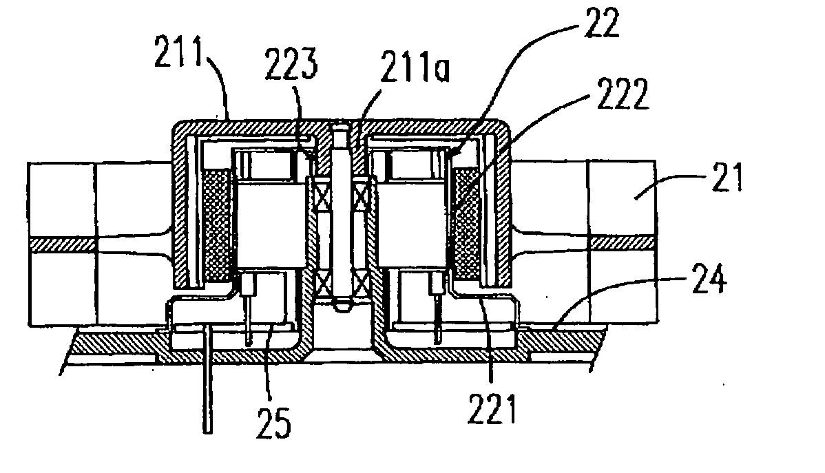
[0027] As shown in FIG. 3, the fan has a stator and a rotor and the moisture-proof device 22 of the present invention is assembled with the stator which includes the coil 26, the core 23, and the printed circuit board 25 for isolating the stator of the motor from moisture. The fan has a base 24 used to place thereon the stator of the motor. The moisture-proof device includes a covering member constructed by a first covering part 211 and a second covering part 222. The first covering part 221, which is hollow, is adhered to the base 24 by an adhesive for covering the circuit board 25 of the stator of the motor. In addition, the second covering part 222, which is hollow, is connected to the first covering part 221 for covering the core 23 and the coil 26. The covering member further has a dented hole 223 telescoped to a protrusion 211a formed inside the hub 211 of the rotor 21 and allows the shaft of the fan to pass therethrough and the moisture-proof device 22 is disposed inside the hub 211 of the rotor 21. Therefore, the first covering part 221 is used for covering the printed circuit board 25, and the second covering part 222 is used for covering the core 23 and the coil to achieve the moisture-proof effect.
[0028] As shown in FIG. 4, the moisture-proof device of the present invention is covered on the stator of the motor. The assembly of the moisture-proof device and the stator can be bonded together via an adhesive. Specifically, the first covering part 221 is shaped as an annular plate, and the second covering part 222 is shaped as a cylinder. Due to the required amount of the adhesive for the present invention is much less than that of the prior art, it will save a lot of the baking time of the process. Therefore, the present invention will largely increase the production capacity.
[0029] As shown in FIG. 5, the first covering part 221 of the moisture-proof device 22 is adhered to the base 24. Preferably, the second covering part 222 can be integrally formed with the first covering part 221 as a single piece. Therefore, the moisture-proof device 22 can completely cover the stator including the core 23, coil 26 and the printed circuit board therein and is positioned inside the hub of the rotor. This present invention not only can provide a good moisture-proof effect but greatly reduce the occupied space of the fan, and the production cost of the moisture-proof device.
[0030] Certainly, the covering member including the first covering part 221 and the second covering part 222 can be connected to the base 24 by engagement or other similar ways. In addition, the fan can be a blower, an axial flow fan and so on.
[0031] Due to the fact that the moisture-proof device of the present invention is directly used as a mask to cover the stator, it will avoid the long-time baking step of the prior art for drying the adhesive layer. Thus, the present invention can increase the production efficiency.
[0032] In sum, the improvement of the structure of the present invention is indeed able to simplify the production operation and increase production efficiency. The present invention is inventive, progressive, and practical.
[0033] While the invention has been described in terms of what are presently considered to be the most practical and preferred embodiments, it is to be understood that the invention need not to be limited to the disclosed embodiment. On the contrary, it is intended to cover various modifications and similar arrangements included within the spirit and scope of the appended claims which are to be accorded with the broadest interpretation so as to encompass all such modifications and similar structures.

PUM

no PUM

Description & Claims & Application Information

We can also present the details of the Description, Claims and Application information to help users get a comprehensive understanding of the technical details of the patent, such as background art, summary of invention, brief description of drawings, description of embodiments, and other original content. On the other hand, users can also determine the specific scope of protection of the technology through the list of claims; as well as understand the changes in the life cycle of the technology with the presentation of the patent timeline. Login to view more.

Similar technology patents

Musculo-skeletal implant having a bioactive gradient

ActiveUS20060045903A1Good effectEnhances chemotactic propertyPharmaceutical delivery mechanismLigamentsActive agentMusculoskeletal implant
Owner:DEPUY SPINE INC (US)

Classification and recommendation of technical efficacy words

Why Eureka
Try Eureka