Ink jet printheads

a technology of ink jet printers and printheads, which is applied in the direction of printing and inking apparatus, etc., can solve the problems of time-consuming, art ink jet printers suffer from a number of deficiencies, and the ability to quickly print a high resolution grain free image, etc., to achieve cost savings, enhance print quality, and prolong the life

Active Publication Date: 2005-01-20
FUNAI ELECTRIC CO LTD
View PDF17 Cites 65 Cited by
  • Summary
  • Abstract
  • Description
  • Claims
  • Application Information

AI Technical Summary

Benefits of technology

[0011] Another aspect of the invention, provides a printhead for an ink jet printer including a semiconductor chip containing a plurality of heater resistors for ink ejection, a power field effect transistors (FET's) for driving each heater resistor, and CMOS logic devices coupled to the FET's and heater resistors. A gate oxide layer for gates of the FET's has a thickness greater than a gate oxide layer for gates of the CMOS logic devices.
[0012] Improvements set fo

Problems solved by technology

However, as set forth in more detail below, these prior art ink jet printers suffer from a number of deficiencies.
One deficiency of prior art ink jet printers is their ability to quickly print a high resolution grain free image.
However, expelling a large number of drops of ink is time consuming and requires advanced addressing schemes.
Thus, high resolution prior art ink jet printers have had relatively low print rates in terms of pages printed per minute.
In addition, a large number of high energy pulses are required to rapidly vaporize the ink droplets.
These frequent high energy pulses result in excessive heating of the printhead.
Excessive printhead temperatures may cause or increase the amount of air bubbles formed in the ink and thereby resulting in poor print quality and/or damage to the thin-film structure of the ink ejector.
However, these prior approaches tend to be overly complex and prone to failure.
In addition, many of the approaches excessively increase the cost of manufacturing the printheads.
These electrical connections increase the cost of producing the printhead cartridge and the likelihood that one of the connections will not be properly completed or will be damaged during the printhead manufacturing process.
Furthermore, the large numbers of small nozzles on a high resolution ink jet printhead are prone to manufacturing defects and clogging.
Unfortunately, the malfunctioning of a single ink jet nozzle severely affects the print quality of the image produced by the printer.
The need to rapidly expel a large number of ink droplets in a short amount of time also leads to electromigration problems in the heater chip of the ink jet printer.
This movement of the aluminum will eventually cause the heater chip to malfunction due to a short or open circuit.
Unfortunately, electromigration is more pronounced at the relatively higher current densities that are required for high resolution, high speed printing.
Prior art ink jet printers are also deficient in that the firing resistors used to

Method used


Image

  • Ink jet printheads
  • Ink jet printheads
  • Ink jet printheads

Examples


Embodiment Construction

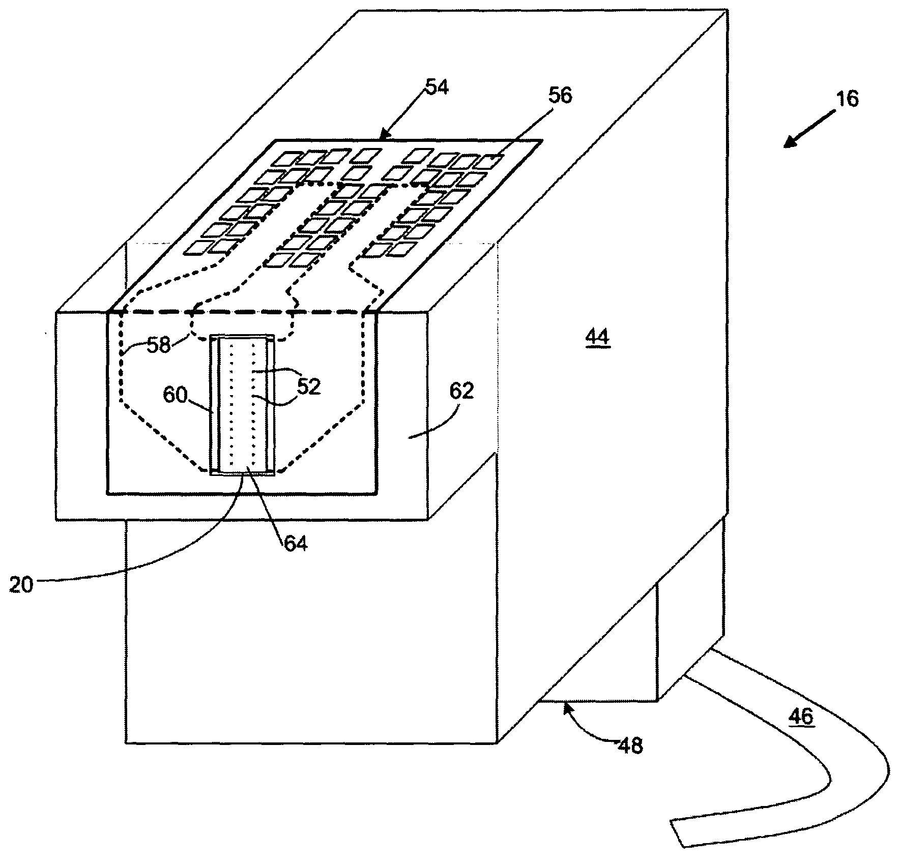
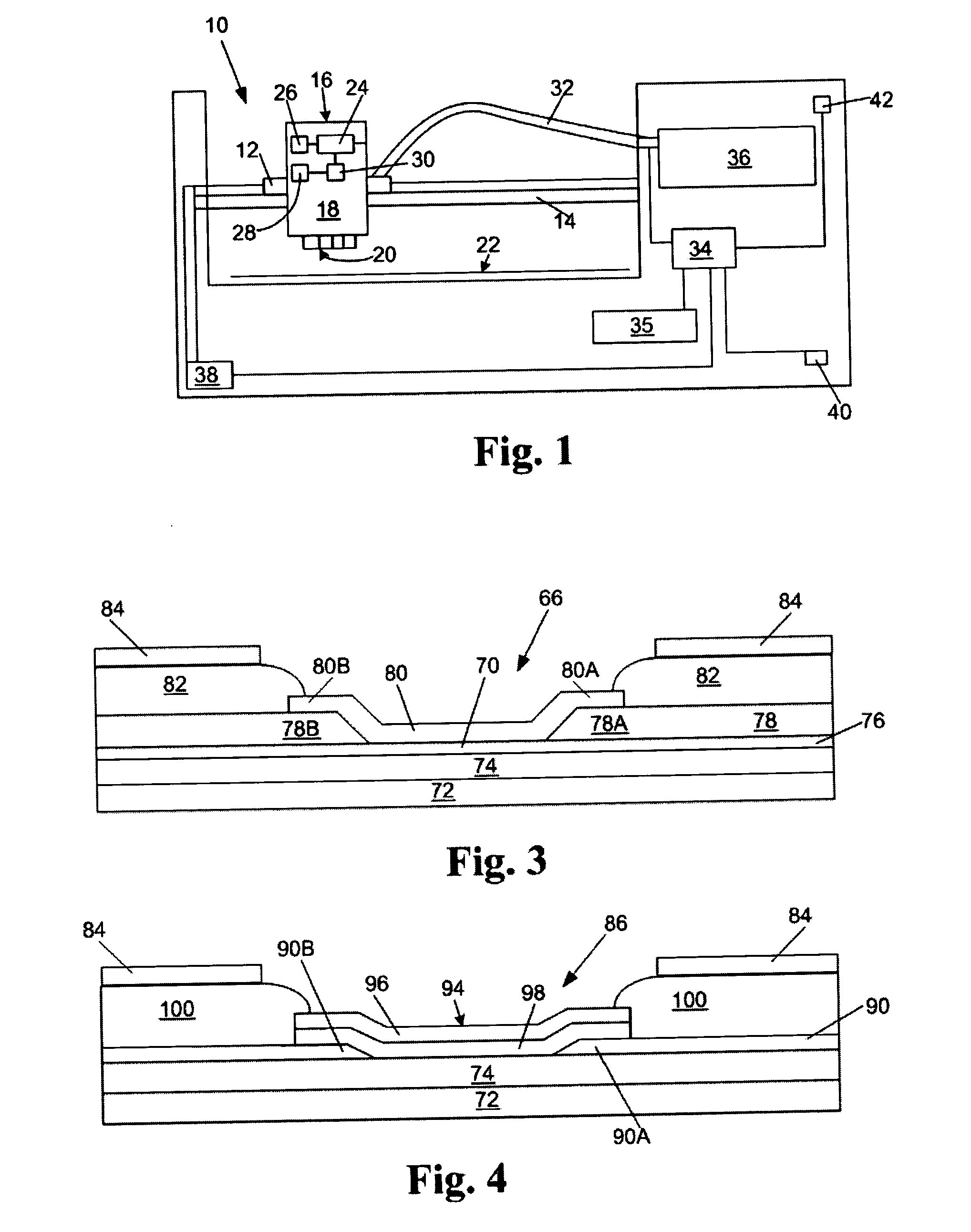
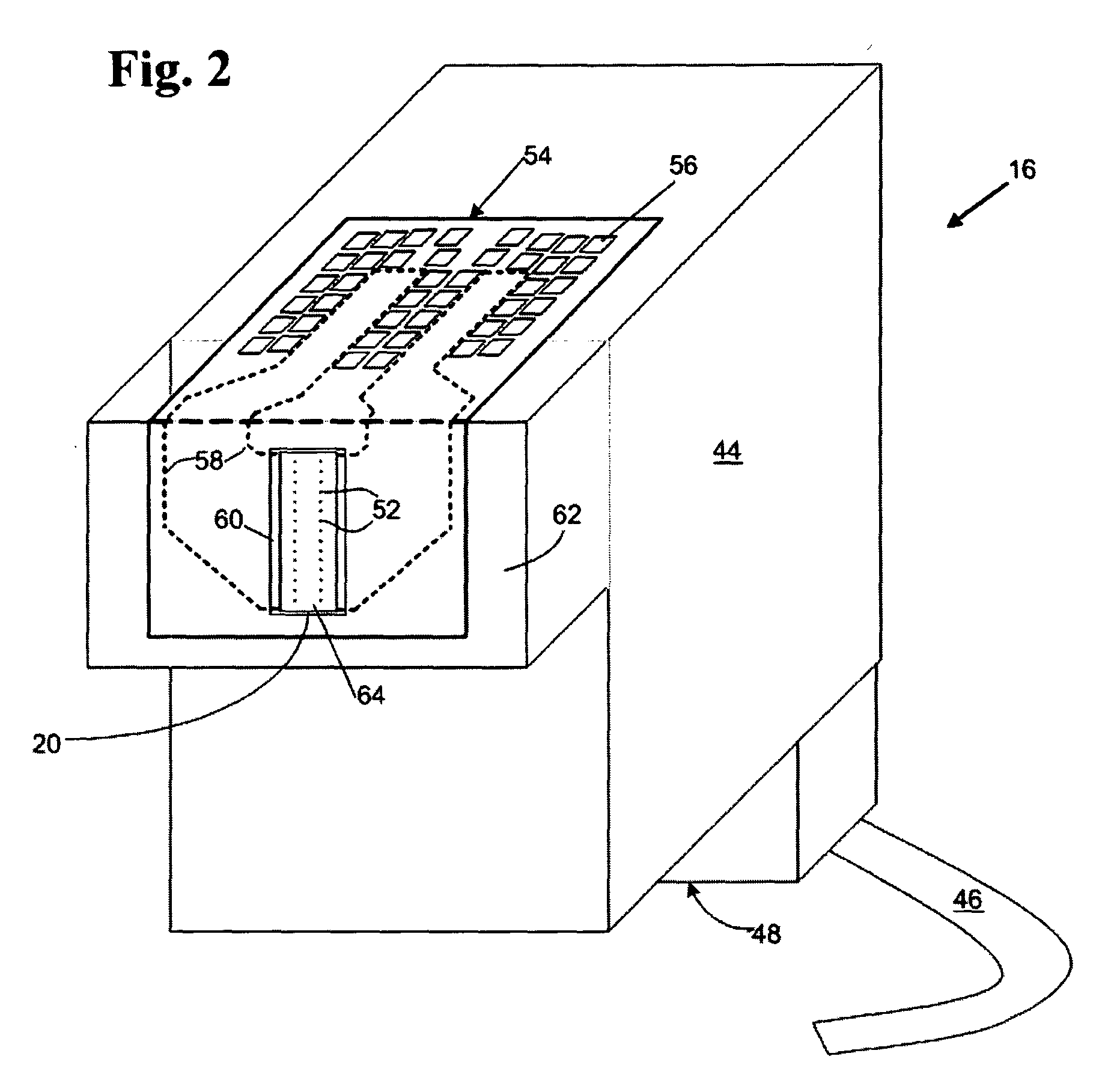
[0033] The present invention is directed toward a novel combination of new and prior art ink jet printing concepts that is adapted to provide a faster, more reliable ink jet printer that is less expensive to produce than prior art designs. As shown in FIG. 1, an ink jet printer 10 constructed in accordance with the present invention utilizes a printhead carriage 12 that is movably mounted on a support member 14. A semi-permanent printhead cartridge 16 is installed on the printhead carriage 12. While a single printhead cartridge 16 is shown, it will be readily apparent to those skilled in the art that a color ink jet printer may utilize multiple printhead cartridges each having an ink reservoir containing one of the primary colors selected from cyan, magenta, yellow, and black, or a single printhead cartridge containing a multi-color printhead and associated ink reservoirs for the primary colors. However, for purposes of simplicity, the printhead cartridge 16 in FIG. 1 is shown with ...


PUM


Abstract

An ink jet printer including a printer cartridge containing a printhead attached to a cartridge carriage for translation of the cartridge across a print media. The printer also includes an off carriage ink supply, a printer microprocessor, and a combined ink fill tube and electrical connection cable connected between the cartridge and the off carriage ink supply for providing refill ink to the ink cartridge and control of the carriage and printhead. Improvements to the printer enable low cost, high quality printing to be achieved.

Description

FIELD OF THE INVENTION [0001] The present invention is generally directed to improved ink jet printers and components therefor. More particularly, the invention is directed to an improved configuration for an ink jet printhead that prints faster and is more reliable and energy efficient than prior art printheads. BACKGROUND OF THE INVENTION [0002] Ink jet printers produce images by expelling droplets of inks from an ink reservoir onto printing medium. The droplets of ink are typically expelled or fired from an array of nozzles in a thick film nozzle plate by nucleating a volume of ink in an ink chamber beneath the nozzle plate with a thin film firing resistor. The nucleation of the ink produces a sudden pressure increase inside of the ink chamber. This increase in pressure forces a droplet of ink from a nozzle positioned adjacent the ink chamber onto the printing medium. Piezoelectric elements may also be used to expel the droplets of ink onto the printing medium by applying a volta...

Claims


Application Information

Patent Timeline
IPC IPC(8): B41J2/14B41J2/175
CPCB41J2/14129B41J2/17506B41J2202/13B41J2/17556B41J2202/03B41J2/17513
Inventor ANDERSON, FRANK E.BELL, BYRON V.SULLIVAN, CARL E.COOK, PAUL A.CORNELL, ROBERT W.PARISH, GEORGE K.
Owner FUNAI ELECTRIC CO LTD
Why Eureka
Try Eureka