Kneading disk, a disk element and a kneading process

a technology of kneading disk and disk element, which is applied in the direction of mixing/kneading with horizontally mounted tools, clay mixing apparatus, rotary stirring mixers, etc., can solve the problems of short pass, non-uniform quality of kneaded mixture, and conventional kneading screws, etc., and achieve low resin temperature

Active Publication Date: 2005-01-20
JAPAN STEEL WORKS LTD
View PDF8 Cites 31 Cited by
  • Summary
  • Abstract
  • Description
  • Claims
  • Application Information

AI Technical Summary

Benefits of technology

[0024] An object of the invention is to provide a kneading disk and a kneading process which do not employ any kneading screw having a blocking effect produced by a return wing, a reverse flight, a neutral wing, a seal ring, etc., but rely only upon a feed wing for exhibiting an optimum kneading condition, i.e. functions of dispersion and distribution and can keep a low resin temperature during kneading.

Problems solved by technology

The conventional kneading screws have, however, presented problems as pointed out below.
The rotor type screw has a high effect of dispersion mainly by the flight tips, but also has a high power of transporting dough due to the continuous flight tips and is likely to cause a short pass easily.
In other words, the rotor type screw gives a good dispersion of dough after its passage of the flight tips and keeps a low resin temperature owing to a short pass, but is likely to produce a kneaded mixture of non-uniform quality.
On the contrary, the kneading disk type screw can produce a uniformly kneaded mixture owing to a high efficiency of dough passage to the flight tips, but is likely to cause a resin temperature elevation due to a dwell time prolonged by the back streams through the clearances between the discontinuous flight tips on every two adjoining disk elements.

Method used


Image

  • Kneading disk, a disk element and a kneading process
  • Kneading disk, a disk element and a kneading process
  • Kneading disk, a disk element and a kneading process

Examples


first example

[0063] This is an example relating to the kneading of talc with a resin for which the satisfactory feeding of talc is required.

[0064] A kneading disk according to the invention and a conventional kneading disk were compared in a capacity of feeding talc, or productivity in a process for kneading 20% of talc with polypropylene (PP) pellets having a melt index of 30 g / 10 min.

[0065] The screw construction was of such a type that talc was added by a side feeder after the melting of PP.

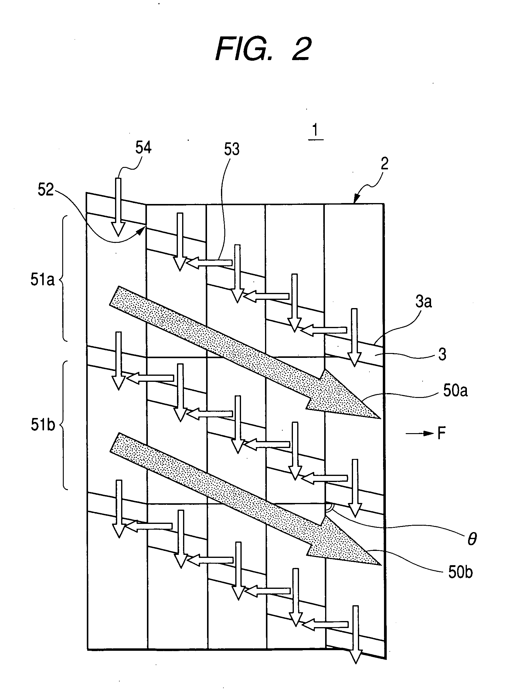
[0066] The kneading disk according to the invention was a kneading disk 1 of the improved productivity type according to the first embodiment and having the flight tips 3 arranged at a helix angle θ of 75° in a direction supporting the main streams 50a and 50b of the resin.

[0067] A kneading disk having a helix angle θ of 0° was prepared as the conventional screw used for comparison.

[0068]FIG. 4 shows the results of comparison in the amounts of production of a kneaded resin as obtained by using the kne...

second example

[0071] This is an example relating to the kneading of carbon black with a master batch for which a good dispersion of carbon black is required.

[0072] A kneading disk according to the invention and a conventional kneading disk were compared in the dispersion of carbon black in a process for kneading 40% of carbon black with low density polyethylene (LDPE) pellets having a melt index of 20 g / 10 min.

[0073] The screw construction was of such a type that carbon black was added by a side feeder after the melting of LDPE.

[0074] The kneading disk according to the invention was a kneading disk according to the second embodiment and having the flight tips 13 arranged at a helix angle θ of 105° in a direction blocking the main streams 60a and 60b of the resin.

[0075] A kneading disk having a helix angle θ of 0° was prepared as the conventional screw used for comparison.

[0076] The screw was driven at a rotating speed of 200 rpm.

[0077]FIG. 5 shows the results of comparison in the dispersion...


PUM

PropertyMeasurementUnit
helix angleaaaaaaaaaa
shift angleaaaaaaaaaa

Abstract

A kneading disk has a plurality of disk elements having flight tips arranged at a helix angle E in a direction supporting main streams of a resin. The flight tips of every two adjoining disks have a clearance formed therebetween. The resin is kneaded by undergoing dispersion and distribution without having any excessive temperature elevation in approximately three kinds of streams, i.e. its main streams flowing along the flight tips, its back streams through the clearances and its tip riding streams flowing over the flight tips.

Description

[0001] This application is base on Japanese Patent Application No. 2003-276016, which is incorporated herein by reference. BACKGROUND OF THE INVENTION [0002] 1. Field of the Invention [0003] The present invention relates to a kneading disk for a co-rotating twin-screw kneader or extruder used mainly for kneading plastic, a disk element therefor and a kneading process. [0004] 2. Description of the Related Art [0005] It has hitherto been usual to combine a feed wing, a return wing, a reverse flight, a seal ring, a neutral wing, etc. for a kneading screw used in a kneader or extruder for plastic to realize an intended kneading performance. [0006] The feed and return wings are of the rotor type in which the flight tips of a kneading screw form a continuous helix, or of the kneading disk type which is composed of multiple disk elements arranged along a screw axis and having flight tips arranged discontinuously and helically in parallel to the screw axis. Kneading is performed mainly by t...

Claims


Application Information

Patent Timeline
Patent Type & Authority Applications(United States)
IPC IPC(8): B29B7/46B29C48/58B29C48/67
CPCB29C47/0009B29C47/64B29C47/60B29C47/0825B29C48/03B29C48/2564B29C48/67B29C48/58
Inventor KAKIZAKI, JUNODA, KATSUHIROSHINTANI, HIROAKI
Owner JAPAN STEEL WORKS LTD
Why Eureka
Try Eureka