Method of CT beam hardening calibration

a beam hardening and calibration method technology, applied in tomography, instruments, applications, etc., can solve problems such as image information loss, beam hardening calibration performed according to spectrum functions (sf) provided by the tube manufacturer may not yield desirable results, and rays emitted from the tube in an actual system are not uniformly distributed

Inactive Publication Date: 2005-01-20
PHILIPS CHINA INVESTMENT +1
View PDF6 Cites 12 Cited by
  • Summary
  • Abstract
  • Description
  • Claims
  • Application Information

AI Technical Summary

Benefits of technology

In view of the deficiencies existing in the current technologies, this invention presents a method of CT beam hardening calibration that includes obtaining raw data of a first phantom and a second phantom by scanning the first phantom and the second phantom respectively, calculating a first filter material length and a second filter material length according to any spectrum function and the raw data of the first phantom as well as the second phantom, adjusting the spectrum function to make the first filter material length and the second filter material length meet with predefined conditions, calculating a beam hardening curve according to the adjusted spectrum function and the first filter material length and the second filter material length having met the predefined conditions, and processing the raw data by the calculated beam hardening curve to eliminate beam hardening effects. The method of CT beam hardening calibration in the invention can eliminate the effects of filter material on CT imaging, and can perform beam hardening calibration on beams according to actual SF.

Problems solved by technology

Computed tomography reconstruction theory assumes that X-rays emitted from the tube are monochromatic, but this assumption is not the case in a typical system.
Compared with pre-processing calibration methods, post-processing methods for calibration algorithms are more time consuming than pre-processing calibration methods and may cause image information losses, yet there are many post-processing methods emerging in international literature.
Beam hardening calibration performed according to the spectrum functions (SF) provided by the tube manufacturer may not yield desirable results.
The rays emitted from the tube in an actual system are not uniformly distributed.
Thus the attenuation materials that the X-ray beam pass through before arriving at the detected object are also different for different channels, resulting in artifacts if the same beam hardening calibration program is deployed for different channels.

Method used


Image

  • Method of CT beam hardening calibration
  • Method of CT beam hardening calibration
  • Method of CT beam hardening calibration

Examples


Embodiment Construction

The theory and implementation of the invention will be described in detail by referring to the figures herein.

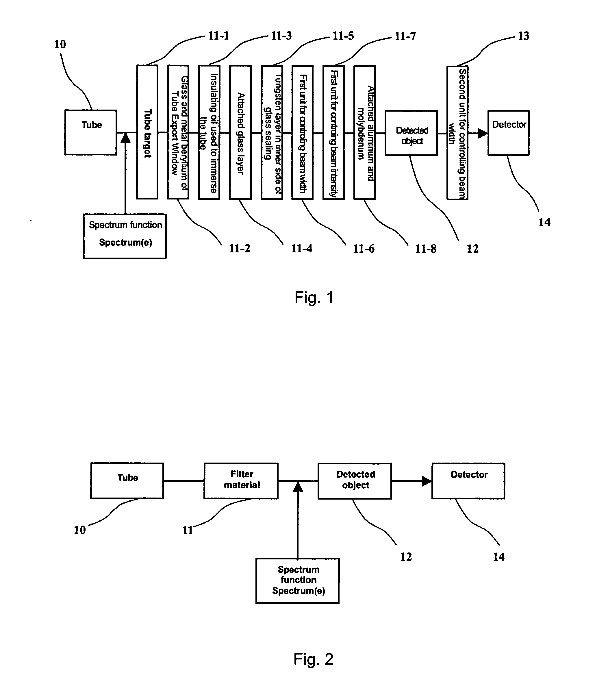
As described above, due to the effects of other filter materials, calibrating directly according to the spectrum functions provided by a tube manufacturer, desirable results are not obtained. Thus, the effects of filter materials must be considered during SF calculation. But if all filter materials are considered separately, the problem is complex to solve and remains indefinite. Hence, a simplification is made of filter materials 11 (i.e. regarding all the filter materials passed through as a black box), and calculations of the SF are made before arriving at the detected object 12, while neglecting the second unit for controlling beam width 13. As shown in the adaptation illustrated in FIG. 2, X-rays pass through the filter materials 11 and detected object 12 from tube 10 to detector 14, with the SF having direct action on the detected object 12 is an SF Spectrum(e) prov...


PUM


Abstract

A method of CT beam hardening calibration comprises: the step of obtaining raw data of a first phantom and a second phantom by scanning the first phantom and the second phantom respectively; the step of calculating a first filter material length and a second filter material length according to one ore more spectrum function and the raw data of the first phantom as well as the second phantom; the step of adjusting said spectrum function to make the first filter material length and the second filter material length agree with predefined conditions; the step of calculating a beam hardening curve according to the adjusted spectrum function and the first filter material length as well as the second filter material length met with the predefined conditions; and the step of processing the raw data by the calculated beam hardening curve to eliminate beam hardening effects. After calibrating raw data by using the adjusted spectrum curve, image results showed that artifacts such as shading dark artifacts and rings artifacts were significantly reduced.

Description

RELATED APPLICATION This application claims priority to Chinese Application No. 03133763.5 filed Jul. 16, 2003. FIELD OF THE INVENTION This invention relates to the field of computed tomography (CT), especially to a method of CT beam hardening calibration that can eliminate the effects of nonlinear factors unrelated to the detected object that is subject to imaging. BACKGROUND OF THE INVENTION A CT tube emits x-rays, which is received by one or more detectors facing the tube. The detectors measure an attenuation value of X-rays between the CT tube and the detectors and calculate a distribution of material according to the attenuation value of a detected object measured from every angle of view as well as in coordination with a reconstruction program. Thus images can be reconstructed by the CT system. Computed tomography reconstruction theory assumes that X-rays emitted from the tube are monochromatic, but this assumption is not the case in a typical system. In fact, the X-rays e...

Claims


Application Information

Patent Timeline
Patent Type & Authority Applications(United States)
IPC IPC(8): A61B6/00A61B6/03G01D18/00
CPCA61B6/03A61B6/583A61B6/4035
Inventor SUN, HAININGLOU, SHANSHANLIU, JINJUN
Owner PHILIPS CHINA INVESTMENT
Why Eureka
Try Eureka