
Artificial heart pump system and its control apparatus

a heart pump and controller technology, applied in the field of artificial heart pump systems and controllers, can solve the problems of lowering productivity and maintainability, high cost of processor software, and and achieve the effect of lowering the complexity of the software in each processor and low cos

Active Publication Date: 2005-01-20
TC1 LLC
View PDF9 Cites 39 Cited by
  • Summary
  • Abstract
  • Description
  • Claims
  • Application Information

AI Technical Summary

Benefits of technology

The present invention proposes an artificial heart pump system with a control apparatus (controller) that has two processors for a control system and a display system. The controller is portable and can control the operation of the blood pump under a preset condition. The system also includes a memory device for recording the operation status of the blood pump. The control apparatus can change the operation condition of the blood pump and has a low complexity software. The system has a plurality of processors that function as a central unit and can continue operating even if one processor fails. The technical effects of the invention are reduced complexity of software, lower cost, and improved safety measures.

Problems solved by technology

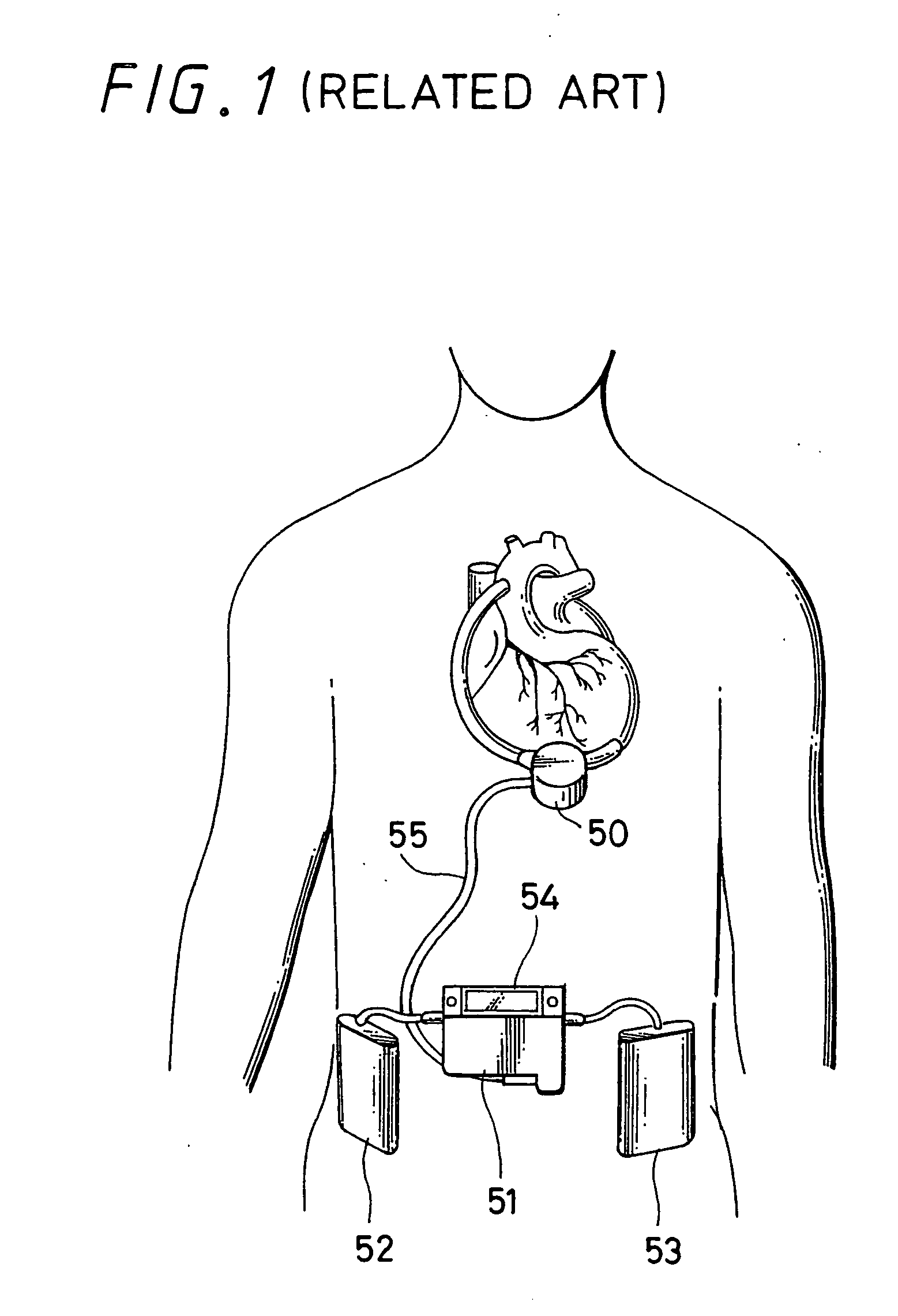
However, the controllers used for the artificial heart pump system which were described in these conventional technologies did not have a processor, were all formed by analog circuits, only a monitor was controlled by a processor even if a processor was included and the control of a motor or a bearing thereof was performed by analog circuits.
In other words, a high cost is requested for the processor.
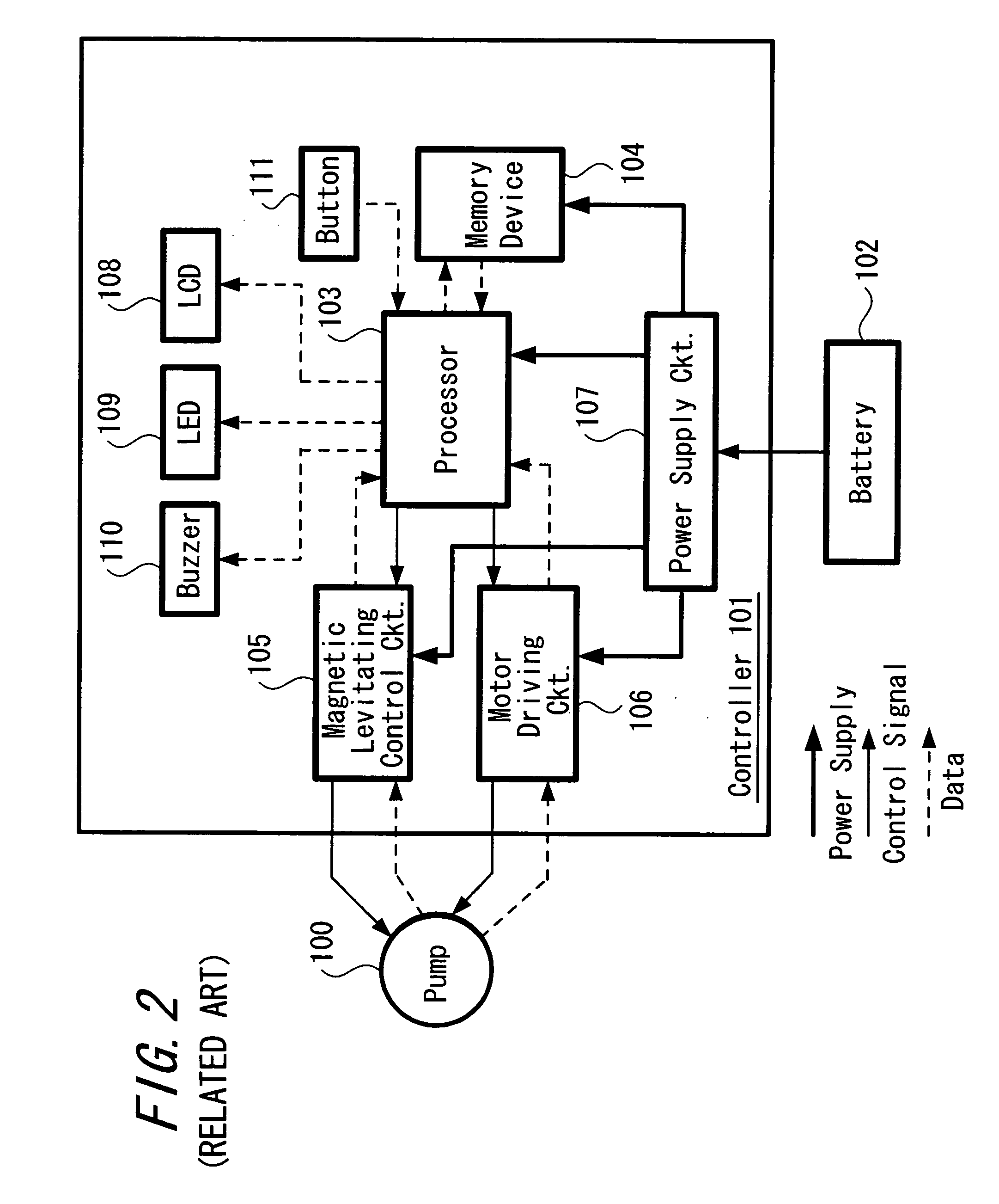
Also, in a case when all the processes are performed by one processor 103 in this manner, the software operated on the processor 103 becomes complicated and consequently, productivity and maintainability will be lowered such that a large amount of cost is to be necessary for keeping them.

Method used


Image

  • Artificial heart pump system and its control apparatus
  • Artificial heart pump system and its control apparatus
  • Artificial heart pump system and its control apparatus

Examples


Embodiment Construction

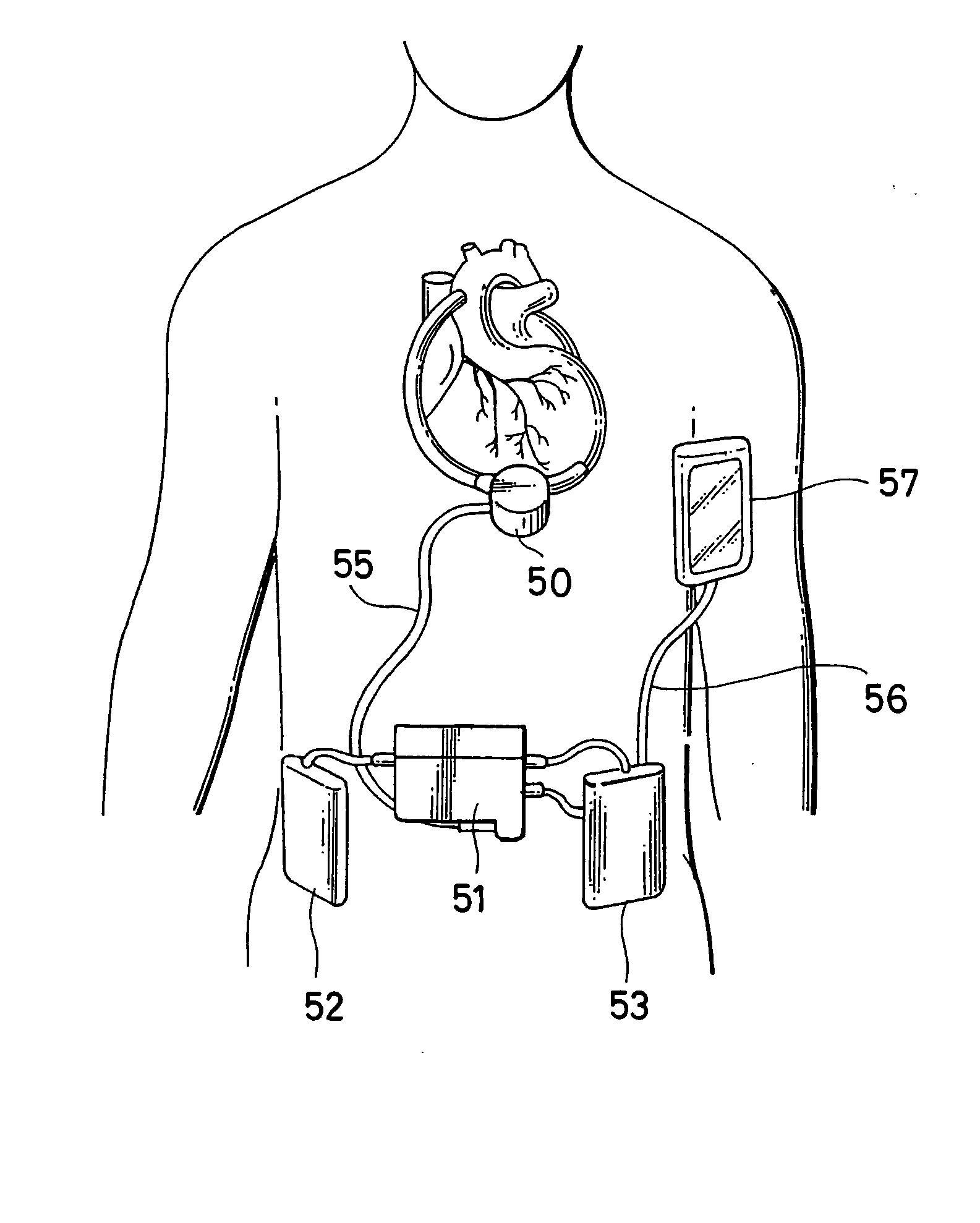
[0047]FIG. 4 is a block constitutional diagram showing an exemplified embodiment of an artificial heart pump system using a multi-processor according to the present invention. This artificial heart pump system is constituted by a controller 1, a blood pump 2 and a battery 3.

[0048] As shown in FIG. 4, the controller 1 is provided with two processors of a controlling processor 4 which supervises the control of a blood pump 2 and a control system in the controller 1 and of an observing processor 5 which supervises the control of a display system. Then, controller 1 is composed, other than aforesaid controlling processor 4 and observing processor 5, of a magnetic levitating control circuit 6 for levitating an impeller in the blood pump 2 magnetically and controlling its levitating position; a motor driving circuit 7 for driving a motor which rotates the impeller; a memory device 8 for receiving and accumulating data showing an operation status of the blood pump 2 from the observing pro...


PUM


Abstract

An artificial heart pump system is concerned where the load of a processor in a controller used for a blood pump system is reduced and the performance of the hardware is maintained or guarantied, and the artificial heart pump system is provided independently with a controlling processor for controlling an operation status of a blood pump so as to perform in a preset condition and with an observing processor for controlling a display unit displaying an operation status and an operation condition of the blood pump. In addition, a memory device is mounted in an outside-the-body type battery pack included in the artificial heart pump system; data such as pump data, event log or the like is stored therein; and data are collected and managed automatically by a battery charger when charging the battery charger for a daily performance. Further, a user interface unit of an artificial heart pump is proposed where a user can confirm displayed contents of the controller without exposing the controller externally.

Description

BACKGROUND OF THE INVENTION [0001] 1. Field of the Invention [0002] The present invention relates to an artificial heart pump system and a controller utilized for its control and more particularly to an artificial heart pump system where a plurality of processors are provided in the control apparatus and a load burdened in one processor is made reduced. [0003] 2. Description of the Related Art [0004] In a conventional assisted artificial heart pump system, it was proposed a system where a sensor circuit for discriminating a levitating position of an impeller is built-in in a pump body in order to establish compatibility between a blood pump body and a controller which are used for an artificial heart (see Jap. laid-open Pat. No. 2001-327595). [0005] Also, as a control method of a blood pump used such as for an artificial heart and for an artificial heart and lung where of the blood pump is assisting or completely displacing a living-body heart by being bypass connected, there was kn...

Claims


Application Information

Patent Timeline
Patent Type & Authority Applications(United States)
IPC IPC(8): A61M1/10A61M1/12
CPCA61M1/101A61M1/122A61M2205/3523A61M1/127A61M60/148A61M60/216A61M60/178A61M60/592A61M60/822
Inventor SUGIURA, NAOYA
Owner TC1 LLC
Learn More