

Plating system with multiple function drill guide
a technology of plate hole and drill guide, which is applied in the field of bone fixation system, can solve the problems of small margin for error in spinal surgery, risk of tissue damage, and inability to align screws within the plate hole,
- Summary
- Abstract
- Description
- Claims
- Application Information
AI Technical Summary
Benefits of technology
Problems solved by technology
Method used
Image

Examples
Embodiment Construction
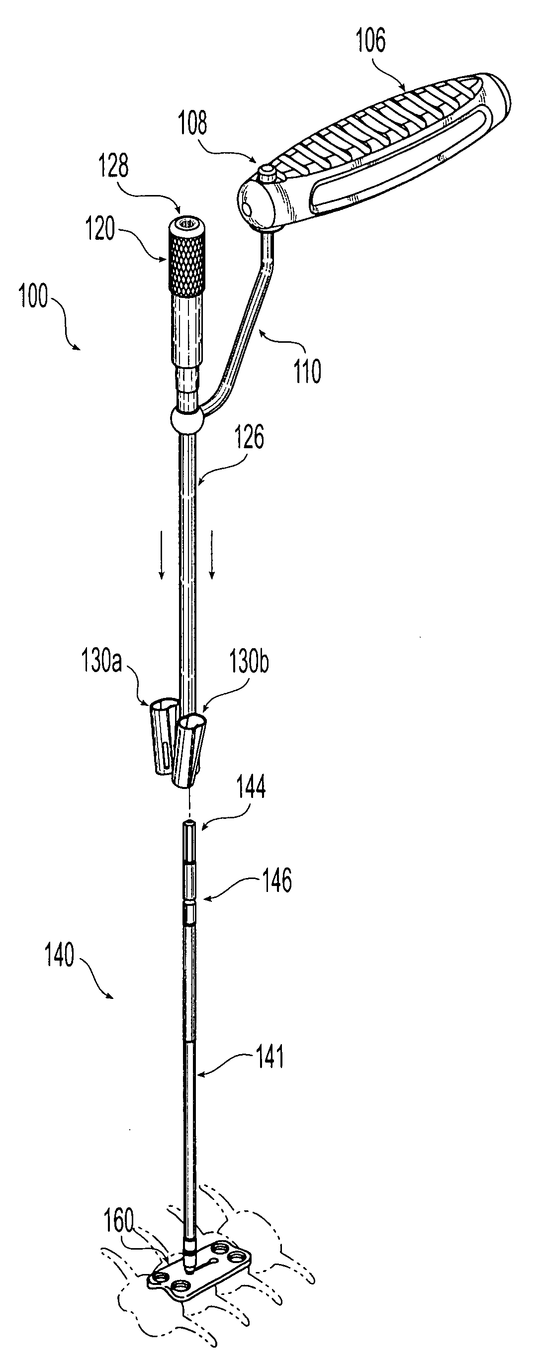
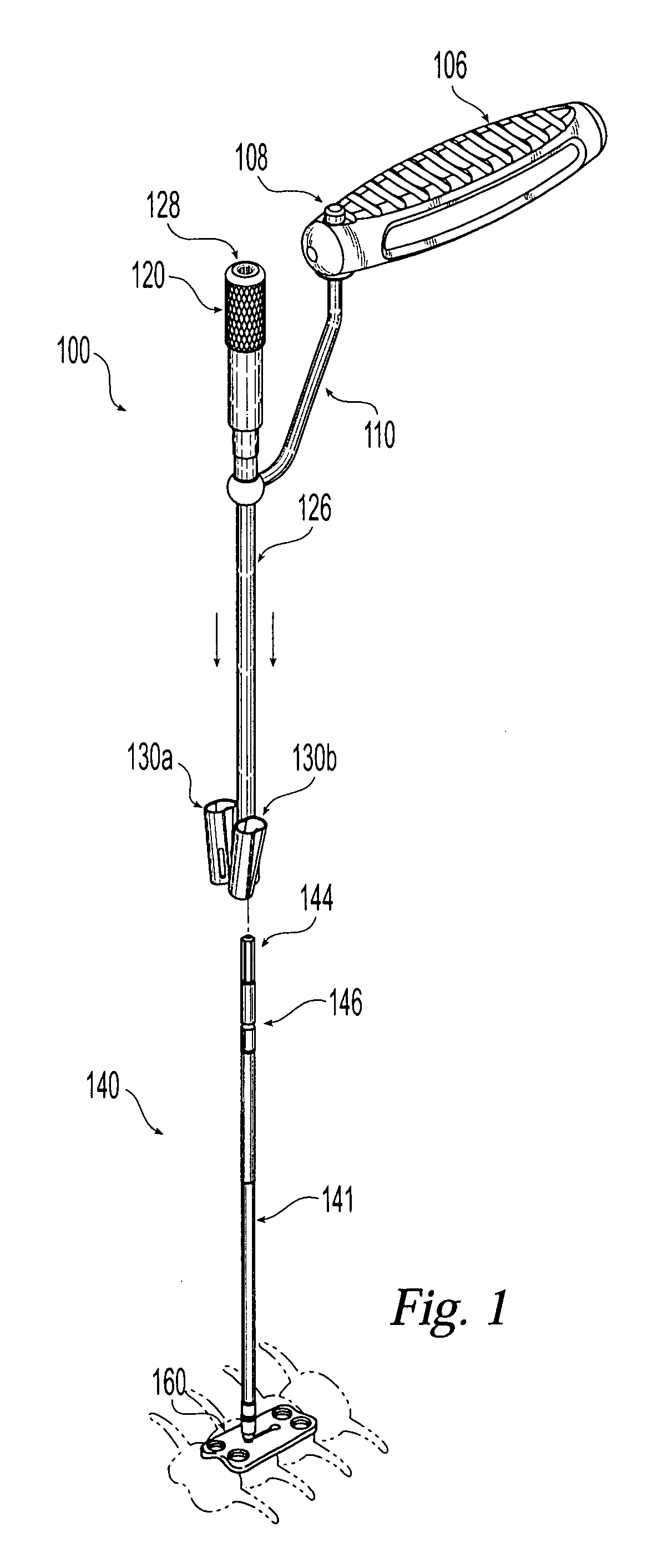
[0028] Referring to FIG. 1, there is shown an exemplary double barrel drill guide assembly 100 and plate holder 140, which are adapted for use with a slotted cervical spine locking bone plate 160. While the bone plate, and plate holder and drill guide assembly are shown and described as a cervical plate for use in the cervical region of the spine, it will be appreciated that the bone plate features are applicable to other bone plates and that the drill guide assembly and plate holder are also usable with other bone plates. Assembly 100 includes a handle member 106, an offset handle stem 110, release sleeve 120, outer stem 126, and drill guiding barrels 130a and 130b. Handle member 106 of drill guide assembly 100 can be incrementally swiveled by pressing and holding button cam 108. Releasing the button cam 108 locks handle 106 in place with relation to offset handle stem 110.
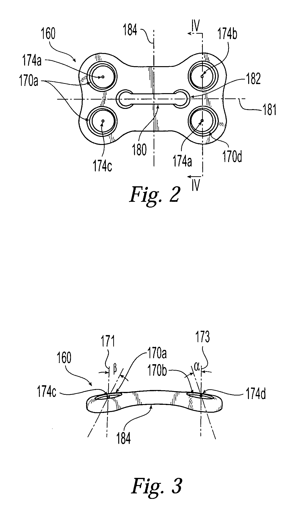
[0029] With reference to FIG. 2, cervical spine locking bone plate 160 is roughly dog-bone shaped with two pa...
PUM
 Abstract
Description
Claims
Application Information