Embolization device and a method of using the same

a technology of embolization device and embolization method, which is applied in the direction of dilators, prostheses, blood vessels, etc., can solve the problems of vascular spasm, paralysis or other adverse events, toxic to tissue, etc., and achieve the effect of reducing increasing the flexibility of the space-occupying devi

a technology of embolization device and embolization method, which is applied in the direction of dilators, prostheses, blood vessels, etc., can solve the problems of vascular spasm, paralysis or other adverse events, toxic to tissue, etc., and achieve the effect of reducing increasing the flexibility of the space-occupying devi

US20050015110A1Inactive Publication Date: 2005-01-20ENDOLOGIX LLC

Image

  • Embolization device and a method of using the same
  • Embolization device and a method of using the same
  • Embolization device and a method of using the same

Examples


Embodiment Construction

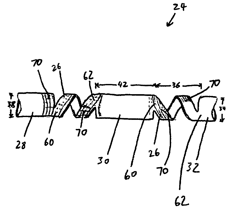
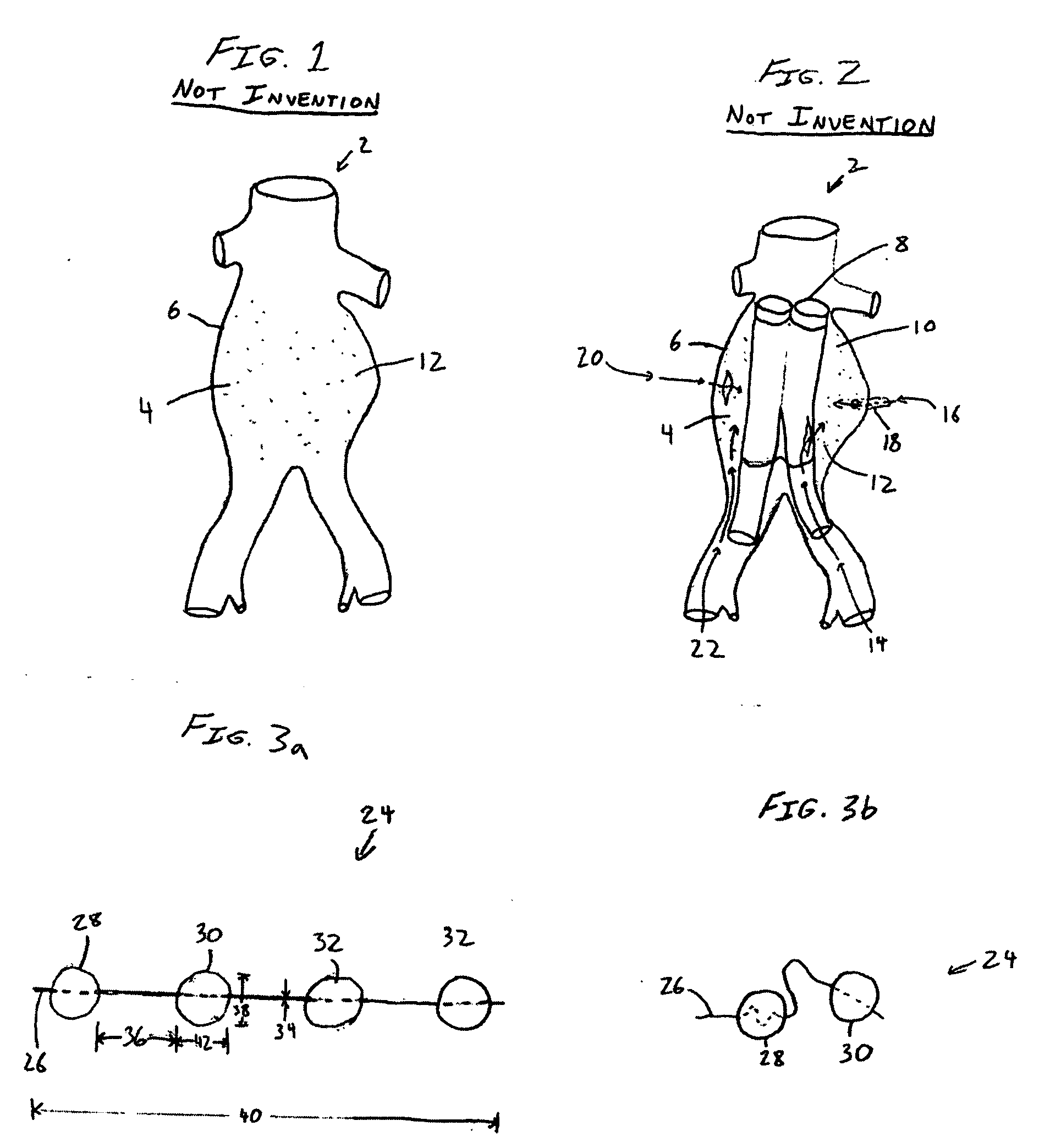
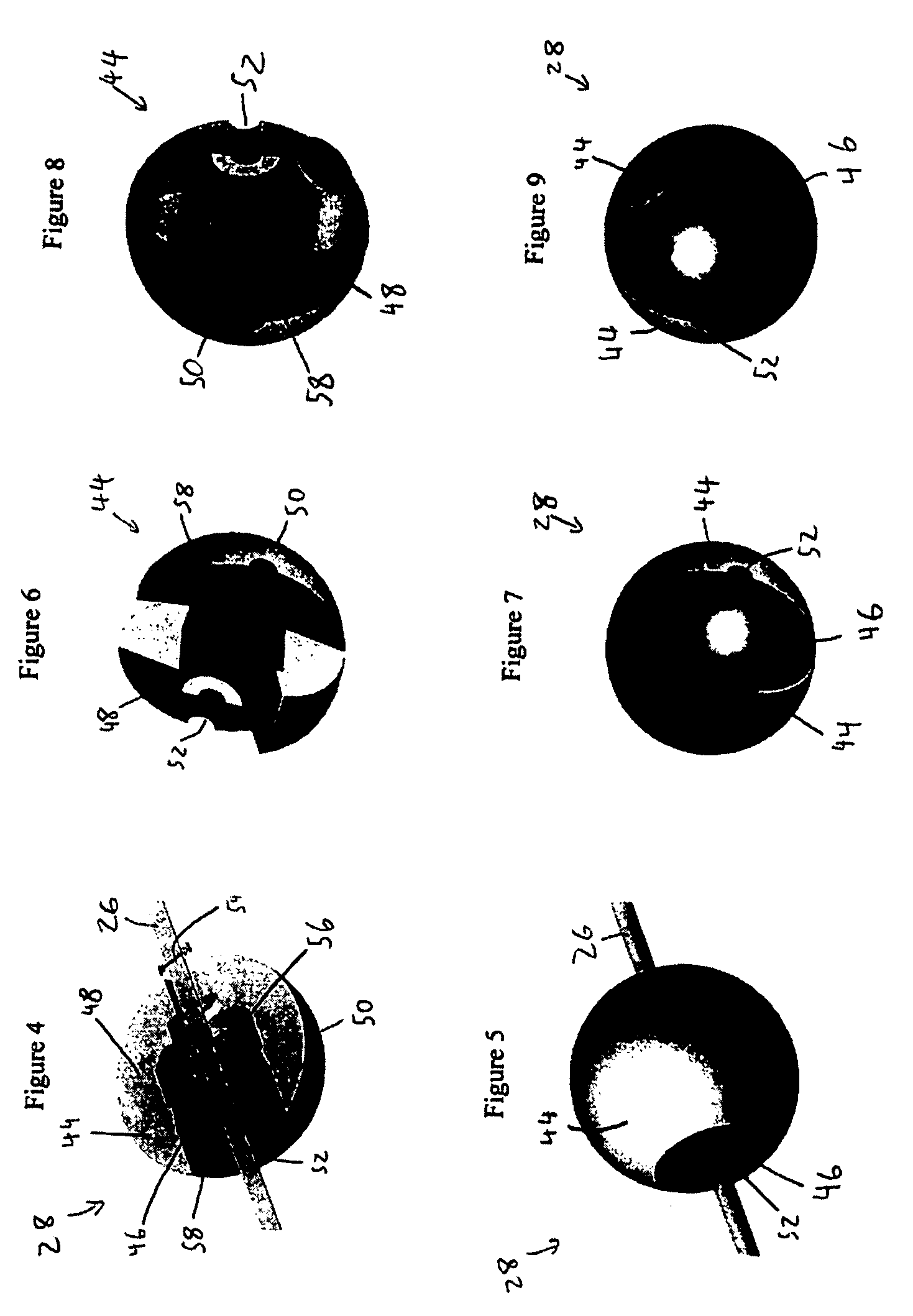
[0051]FIG. 3a illustrates an embodiment of a vascular embolization or occlusion device 24 having a flexible leader 26 that can be connected to a first non-expandable space-occupying element 28 and a second non-expandable space-occupying element 30. Additional non-expandable space-occupying elements 32 can also be connected to the leader 26 and provided in various lengths, depending on the typical volume of the sac 10 to be filled. The leader 26 can pass through the elements 28, 30 and 32. The leader 26 can be fixed to the elements 28, 30 and 32, or the elements 28, 30 and 32 can slide freely over the leader 26. As illustrated in FIG. 3b, the leader 26, even if secured within an element 28, 30, or 32, can flex and bend within each element 28, 30 or 32, or between the elements 28, 30 and 32.

[0052] The leader 26 can be a suture, preformed resilient structure, poppet, wire, fiber, monofilament, rail, or a woven thread or other combination thereof. The leader 26 can be completely separa...


PUM

PropertyMeasurementUnit
diameteraaaaaaaaaa
lengthaaaaaaaaaa
lengthaaaaaaaaaa

Abstract

Space-occupying devices for treating voids within the body are disclosed. The devices can have multiple elements connected to a flexible leader. The devices can be coated by a binding agent. The devices can also be fillable. Methods of making and using the devices are also disclosed.

Description

BACKGROUND OF THE INVENTION [0001] 1. Field of the Invention [0002] The present invention relates generally to a device for filling and / or stabilizing the void within an anatomical organ of the body, particularly within the vasculature, and methods for making and using the device. [0003] 2. Description of the Related Art [0004] An aneurysm is an abnormal dilatation of a biological vessel. Aneurysms can alter flow through the affected vessel and often decrease the strength of the vessel wall, thereby increasing the vessel's risk of rupturing at the point of dilation or weakening. FIG. 1 illustrates an abdominal aorta 2 with a sacular aneurysm 4 having an aneurysm wall 6. FIG. 2 illustrates the abdominal aorta 2 with a vascular prosthesis 8 implanted to treat the aneurysm 4, a common aneurysm therapy. Vascular grafts and stent-grafts (e.g., ANEURX® Stent Graft System from Medtronic AVE, Inc., Santa Rosa, Calif.) are examples of vascular prostheses used to treat aneurysms by reconstruc...

Claims


Application Information

Patent Timeline
20 Jan 2005
Publication
US20050015110A1
IPC
A61B17/12; A61F2/06; A61L31/04; A61M29/00
CPC
A61B17/12022; A61B17/12118; A61B17/12163; A61F2/07; A61F2230/001; A61F2/88; A61F2002/075; A61F2220/0091
Inventors
FOGARTY, THOMAS J.; DREWS, MICHAEL J.