Posterior vertebral joint prosthesis

a technology prosthesis, which is applied in the field of posterior vertebral joint prosthesis, can solve the problems of increasing pain for patients and trauma, difficulty in ensuring quality bearing, and difficulty in ensuring that bearings are placed with quality, so as to improve the contact area of the bone, improve the effect of anchoring and improving the effect of the result of the member

Inactive Publication Date: 2005-01-20
LOUIS CHRISTIAN +1
View PDF15 Cites 256 Cited by
  • Summary
  • Abstract
  • Description
  • Claims
  • Application Information

AI Technical Summary

Benefits of technology

[0007] In another aspect, the invention consists in proposing a device for replacing posterior vertebral joint surfaces, which device comprises, for the left joint and for the right joint, a first prosthesis for the anterior joint process, the first prosthesis including a first smooth bearing surface, and a second prosthesis for the posterior joint process, the second prosthesis including a second smooth bearing surface of a shape that is complementary to the shape of said first surface of the first prosthesis so as to facilitate sliding on the first surface and so as to facilitate relative antero-posterior (or sagittal) pivoting movement between two adjacent vertebrae fitted with these prostheses; this enables two vertebrae fitted with prostheses of the invention to conserve a high degree of mobility.
[0009] Putting said first and second prostheses into mutual contact via their respective smooth V-shaped bearing surfaces encourages mutual guidance of these two prostheses during their mutual sliding displacement, thereby increasing the dynamic stability of a spine in which two adjacent vertebrae are fitted with such prostheses.
[0011] In another aspect, the invention consists in providing posterior vertebral joint prostheses presenting smooth sliding bearing surfaces presenting antero-posterior curvature: said anterior first prosthesis presents (in medial view) a rearwardly-open curved sliding surface, and said posterior second prosthesis presents (in medial view) a forwardly-closed curved sliding surface of curvature equal to (or close to) the curvature of the open surface of the first prosthesis; this facilitates free relative antero-posterior pivoting of two adjacent vertebrae fitted with these prostheses; the antero-posterior radius of curvature of these sliding surfaces can be adapted to the position of the vertebra for which the prosthesis is intended; the magnitude of this radius is preferably selected from a range of 18 millimeters (mm) to 28 mm, more preferably 20 mm to 26 mm, and in particular close to 23 mm.
[0015] The invention makes it possible to obtain prostheses that are well adapted to human anatomy, that are compact, stable, and not very traumatizing.
[0017] Specifically, for an anterior prosthesis, the anchoring that results from this member can be improved by the presence of a rib projecting along a portion of the periphery of the bone bearing surface, thereby increasing contact area with the bone.
[0018] Specifically, for a posterior prosthesis, anchoring can be improved by the presence of two elongate anchor members—such as rods or studs—extending along two substantially orthogonal axes.

Problems solved by technology

Those devices present certain drawbacks: because of the presence of numerous respective bearing faces on the various portions (support, strip, base) of the device on different regions of a vertebra, it is difficult to ensure that bearing takes place with quality that is uniform and satisfactory because of the variations in shape between one vertebra and another and / or one patient and another; in addition, the presence of the base, the anchoring support, and of the various fixing means contributes to increasing the volume of the prosthesis and consequently to increasing the discomfort for the patient and the trauma due to implanting such a device.

Method used


Image

  • Posterior vertebral joint prosthesis
  • Posterior vertebral joint prosthesis
  • Posterior vertebral joint prosthesis

Examples


Embodiment Construction

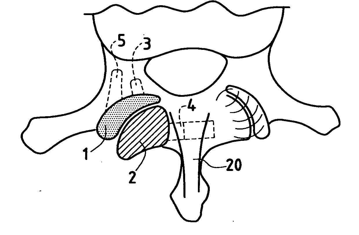
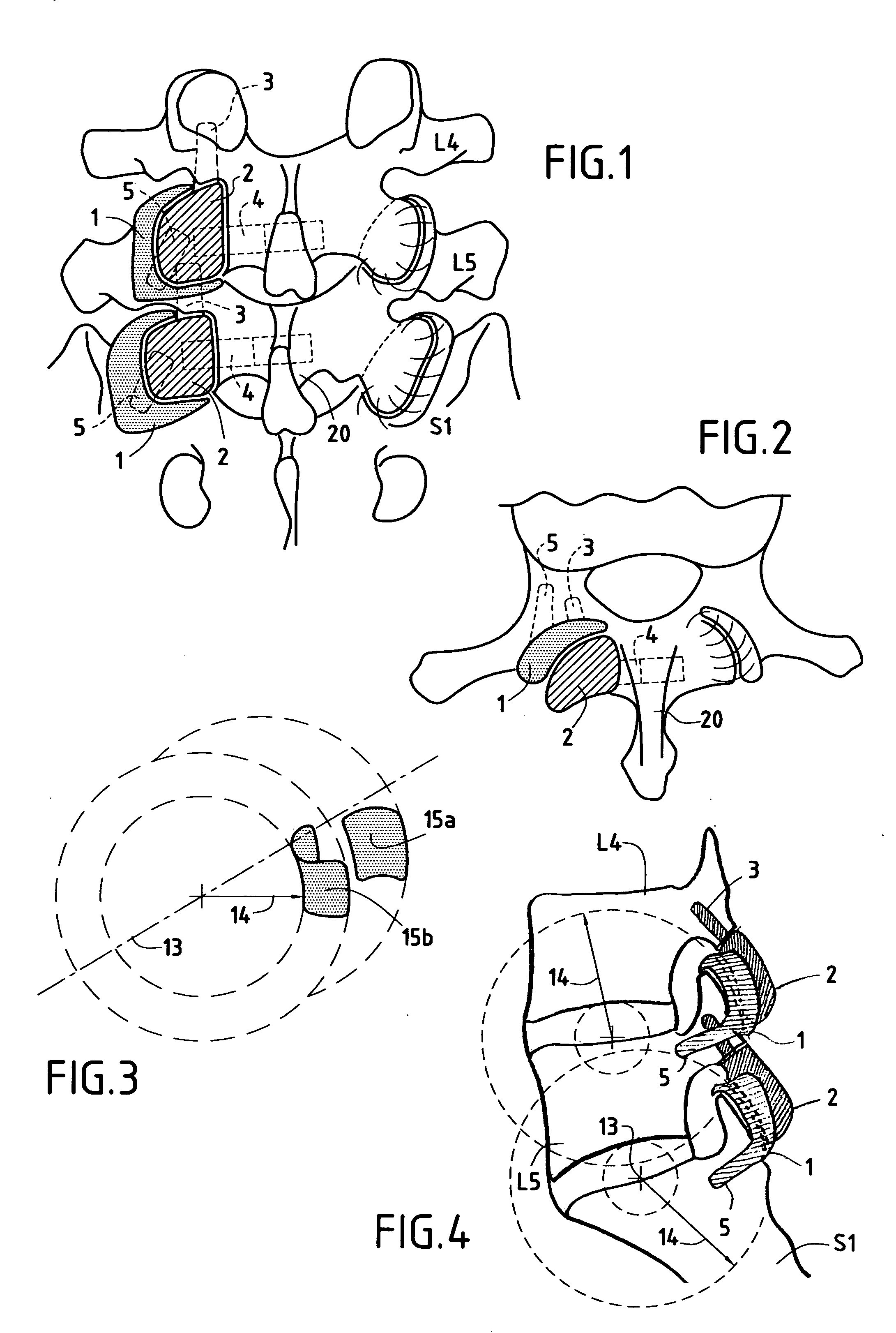
[0029] Although the invention is described below in association with the lumbar portion of the spine, the invention is applicable to the posterior joints of dorsal and cervical vertebrae as well.

[0030] With reference to FIGS. 1 and 2 in particular, a left or right posterior vertebral joint is replaced by using an anterior prosthesis 1 referred to as a “first” prosthesis, and a posterior prosthesis 2 referred to as a “second” prosthesis. The anterior prosthesis 1 is fixed on a vertebra such as L5 or to the sacrum S1, while the posterior prosthesis 2 is fixed to the vertebra situated immediately thereabove, such as L4 or L5, respectively.

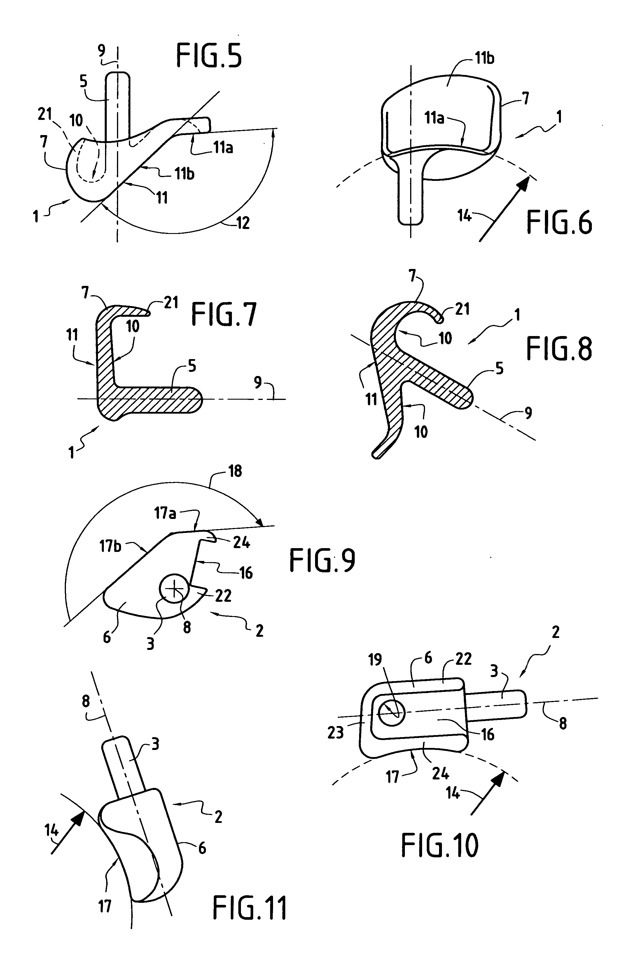
[0031] With reference to FIGS. 5 to 18 in particular, each of the prostheses 1 and 2 comprises a body 6, 7 and a cylindrical anchor rod 3, 5 integrated in the body and elongate along an axis 8, 9.

[0032] With reference to FIGS. 5 to 8 and 12 to 15, the body 7 of the anterior prosthesis 1 is defined to a large extent by two opposite surfaces: a surfa...


PUM


Abstract

The present invention relates to a posterior vertebral joint prosthesis. The left or right posterior vertebral joint prosthesis of the invention presents a smooth bearing surface and said surface presents antero-posterior curvature.

Description

BACKGROUND OF THE INVENTION [0001] Pain in the cervical, dorsal, and lumbar vertebrae often originates from posterior vertebral joints or zygapophysory joints or “facet” joints. When medical therapy is no longer sufficient for easing the pain, in particular when such joints have become very deformed by arthrosis or old trauma, it becomes desirable to replace their joint surfaces by prostheses; the purpose of such prostheses is to conserve the functions and mobility of the vertebral column, and to avoid the joints becoming blocked (arthrodesis). [0002] Documents FR 2 721 501 and U.S. Pat. No. 6,132,464 describe various devices for replacing the joint surfaces of posterior vertebral facets; each of those devices comprises a support having a convex face fitting closely and coming into bearing contact against a portion of the concave surface of the posterior arc of a vertebra, on at least one side of the spinous process; the support is fixed to the vertebra by a pedicular screw, and / or ...

Claims


Application Information

Patent Timeline
Patent Type & Authority Applications(United States)
IPC IPC(8): A61F2/30A61B17/58A61F2/44
CPCA61F2/4405A61F2002/30879A61F2002/30878A61F2002/30772
Inventor LOUIS, RENETROPIANO, PATRICKBRONSARD, JEAN-JACQUESLOUIS, CHRISTIAN
Owner LOUIS CHRISTIAN
Why Eureka
Try Eureka