Intervertebral disk and nucleus prosthesis

a technology of intervertebral disks and prostheses, which is applied in the field of human spine prosthesis replacement structures, can solve the problems of disc prosthesis through the endplate into vertebral bone, accelerated degeneration of spinal motion segments, and subsidence of bone grafts, etc., and achieves the effect of reducing the risk of disc deformation and further destabilizing the dis

Inactive Publication Date: 2005-01-20
K2M
View PDF77 Cites 197 Cited by
  • Summary
  • Abstract
  • Description
  • Claims
  • Application Information

AI Technical Summary

Benefits of technology

[0035] A further object is to provide a prosthesis for replacing a human intervertebral disk wherein

Problems solved by technology

Although spinal fusion procedure has been the standard for surgical treatment of chronic low back pain caused by DDD, it has presented significant problems: a) Obtaining successful fusion has not been free of problems.
This, in turn, is the main cause of accelerated degeneration of the spinal motion segment adjacent to the fusion.
Subsidence of a bone graft, intervertebral fusion device, or disk prosthesis through the endplates into vertebral bone has been a frequently reported problem in the reconstructive surgery of the lumbo-sacral spine.
Such problems as subsidence, sclerosis, bone marrow edema, and contour changes are due to abnormal stress patterns between vertebral bone and the disk.
Some of them were clinically tested in humans, and significant problems were found, such as, e.g., extrusion, migration, subsidence and/or adverse changes at the vertebral endplates.
This causes further destabilization of the disc, because the nucleus prosthesis is not designed specifically to restore the function of the annulus fibrosus.
However these prior designs present certain problems.
Spherical balloon prostheses may cause a

Method used


Image

  • Intervertebral disk and nucleus prosthesis
  • Intervertebral disk and nucleus prosthesis
  • Intervertebral disk and nucleus prosthesis

Examples


Embodiment Construction

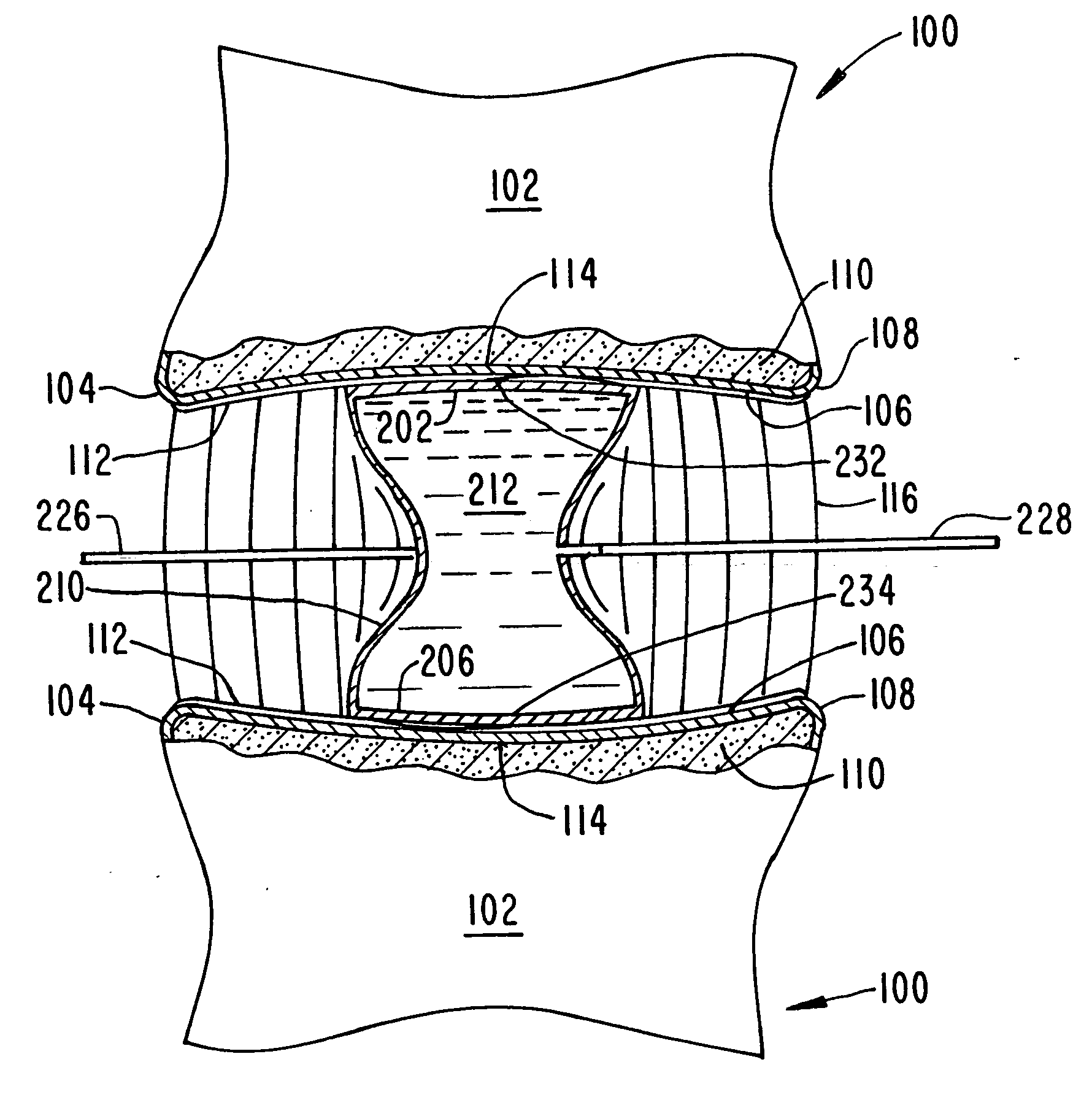
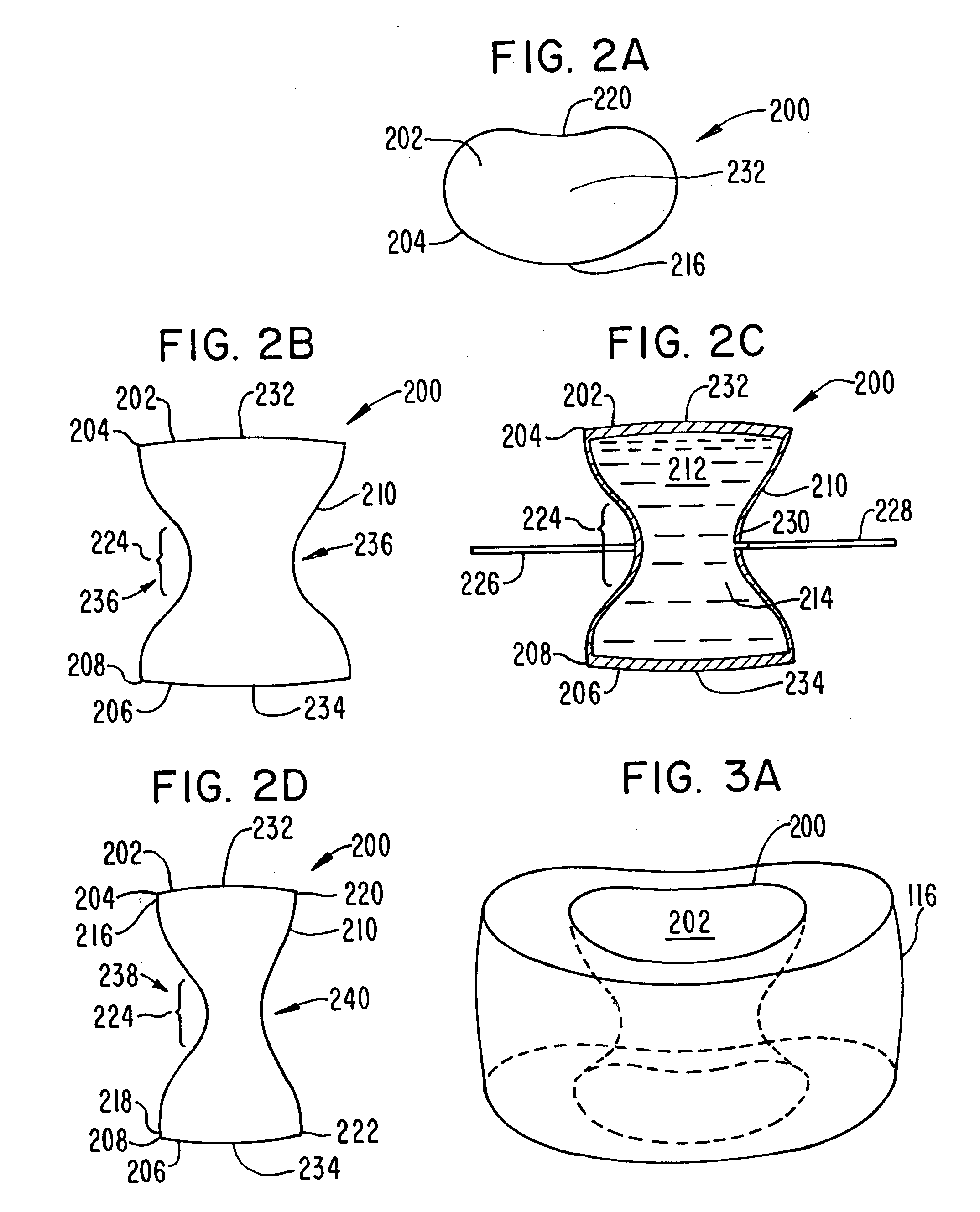
[0082] The invention includes a prosthesis for replacing the nucleus pulposus of a human intervertebral disk and a prosthesis for replacing an entire intervertebral disk.

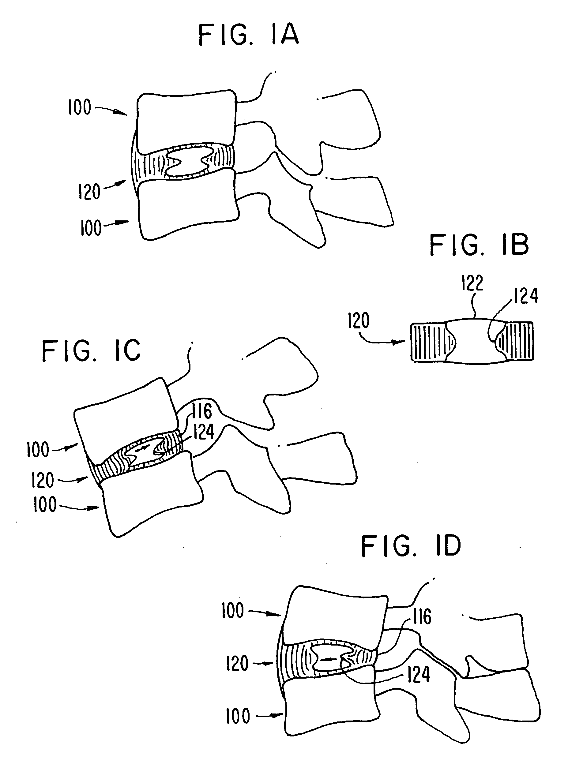
[0083]FIGS. 1A-1D schematically illustrate the natural human intervertebral disk 120, in cross-section, positioned between two vertebrae 100. FIG. 1A shows the configuration of the intervertebral disk 120 when the vertebral column of the spine is in a neutral position. FIG. 1B is a somewhat enlarged cross-section of the intervertebral disk 120, showing the natural nucleus pulposus 122 surrounded by the natural annulus fibrosus 116. The hourglass shape of the natural nucleus pulposus 122 produced by the inwardly bulging inner wall 124 of the natural annulus fibrosus can be seen. FIG. 1C shows the configuration of the intervertebral disk when the spine is in flexion compressing the anterior edge of the annulus fibrosus 116, causing the internal wall 124 to bulge inward, and the posterior edge of the annulus fibrosus ...


PUM

PropertyMeasurementUnit
Fractionaaaaaaaaaa
Fractionaaaaaaaaaa
Fractionaaaaaaaaaa

Abstract

A prosthetic implant for replacing a nucleus pulposus of an intervertebral disk includes upper and lower endwalls of discoid cross-section, each having an antero-posterior diameter less than its transverse diameter, and an hourglass-shaped sidewall connecting the peripheries of the upper endwall and lower endwall to enclose an interior volume filled with a substantially incompressible liquid or soft plastic material. A total prosthesis for replacing the entire human intervertebral disk has an annular core made of a first biocompatible polymer surrounding a central cavity, transitional plates affixed respectively to the upper and lower surfaces of the annular core, the upper and lower transitional plates being made of a second biocompatible material having an elastic modulus greater than that of the first biocompatible polymer, and upper and lower endplates adapted to contact adjacent vertebrae and affixed respectively to the upper and lower transitional plates.

Description

[0001] This application claims the benefit of the priority of U.S. Provisional Patent Application No. 60 / 487,605, filed Jul. 17, 2003, the entire disclosure of which is incorporated herein by reference. This application also claims the benefit of the priority of U.S. Provisional Patent Application No. ______, by Casey K. Lee, entitled INTERVERTEBRAL DISK AND NUCLEUS PROSTHESIS, filed Nov. 26, 2003.BACKGROUND OF THE INVENTION [0002] 1. Field of the Invention [0003] This invention relates to prostheses for replacing structures of the human spine and more particularly to prostheses for replacing an intervertebral disk and / or the nucleus pulposus thereof. [0004] 2. Brief Description of the Prior Art [0005] Lower back pain is a very common disorder and is responsible for extensive morbidity and lost time at work. The prevalence rate of low back pain is very high, affecting approximately 80% of general population at some time. Although most patients experience the painful symptoms only oc...

Claims


Application Information

Patent Timeline
IPC IPC(8): A61F2/00A61F2/30A61F2/44
CPCA61F2/30767A61F2310/00029A61F2/442A61F2002/30383A61F2002/30462A61F2002/305A61F2002/30563A61F2002/30584A61F2002/30604A61F2002/30884A61F2002/444A61F2220/0025A61F2220/0075A61F2310/00017A61F2310/00023A61F2/441A61F2/44
Inventor LEE, CASEY K.
Owner K2M
Why Eureka
Try Eureka