Evaporative deposition method, evaporative deposition head, method for forming pattern of deposition material, and evaporative deposition material disk

a technology of evaporative deposition and pattern, which is applied in the direction of vacuum evaporation coating, solid-state diffusion coating, coating, etc., can solve the problems of low efficiency in use of deposition materials, increase of cost, and long deposition time, and achieve the effect of improving material efficiency

Inactive Publication Date: 2005-01-27
PIONEER CORP
View PDF7 Cites 41 Cited by
  • Summary
  • Abstract
  • Description
  • Claims
  • Application Information

AI Technical Summary

Benefits of technology

[0011] Therefore, one object of the present invention is to provide a method for forming a pattern of deposition material, an evaporative deposition-material disk used in that method, and a fabrication apparatus and a fabrication method of an organic EL display panel, which can achieve the evaporative deposition using no mask so as to eliminate various problems in a case of using the mask, can largely improve the efficiency in use of the material, and can prevent the aforementioned problems in the two maskless methods, of the complicated pre-processing of the transfer plate and the size increase.

Problems solved by technology

However, the former method has a problem in that pre-processing for the transfer plate is added, which results in the increase of the cost.
The former method also has a problem of low efficiency in use of the deposition material because of the deposition material remaining in a region other than the transfer pattern, and a problem of long deposition time.
This leads directly to the increase of equipment cost.
This inevitably increases the size of the evaporative deposition apparatus.

Method used


Image

  • Evaporative deposition method, evaporative deposition head, method for forming pattern of deposition material, and evaporative deposition material disk
  • Evaporative deposition method, evaporative deposition head, method for forming pattern of deposition material, and evaporative deposition material disk
  • Evaporative deposition method, evaporative deposition head, method for forming pattern of deposition material, and evaporative deposition material disk

Examples


Embodiment Construction

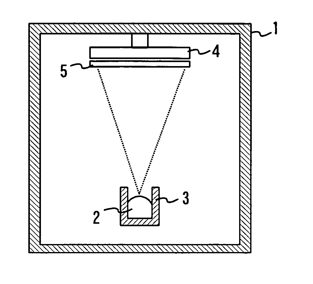
[0055] In general resistance heating evaporative deposition, a deposition material that was heated and sublimed jumps from a boat toward various directions straightly, so as to adhere to a sidewall of an evaporative deposition chamber or a metal mask that is below a sublimation temperature. However, the deposition material that adhered to something jumps again when being heated to the sublimation temperature or higher. The inventor of the present application focuses attention on such a behavior of the deposition material. Thus, the principle of the present invention positively uses a phenomenon that the deposition material adheres to an object below the sublimation temperature. Controlling the temperature of the object can perform the re-sublimation of the deposition material.

[0056] In the evaporative deposition using no mask, a point evaporative deposition source is configured in form of spot having a diameter of several microns and a plurality of such point evaporative deposition...


PUM

PropertyMeasurementUnit
diameteraaaaaaaaaa
diameteraaaaaaaaaa
temperatureaaaaaaaaaa

Abstract

In evaporative deposition method, vaporized deposition material is supplied to a nozzle and is held by the nozzle because of temperature decrease thereof. Then, the deposition material is vaporized by heating the nozzle, thereby forming a thin film of the material on a substrate. A evaporative deposition apparatus includes a nozzle for holding deposition material. The apparatus also includes a temperature adjuster for heating and cooling the nozzle and a supplier, communicating with the nozzle, for supplying the vaporized deposition material to the nozzle. A method for forming a pattern of deposition material includes: preparing an evaporative deposition-material plate including a thin film of deposition material formed on one principal surface of a light-transmitting plate; moving the evaporative deposition-material plate within a plane parallel to a substrate; and irradiating the evaporative deposition-material plate with a laser beam incident on the other principal surface of the plate.

Description

BACKGROUND OF THE INVENTION [0001] 1. Field of the Invention [0002] The present invention relates to an evaporative deposition method, an evaporative deposition head and a method for forming a pattern of deposition materials, more particularly, to an evaporative deposition-material disk used for such pattern forming method. Moreover, the present invention relates a fabrication method and a fabrication apparatus for fabricating an organic electroluminescence display panel that includes a plurality of organic electroluminescence devices each of which has at least one organic layer containing a light emitting layer and is interposed between a pair of electrodes under the utilization of such pattern forming method. [0003] 2. Description of the Related Art [0004] An organic electroluminescence device uses an organic compound that exhibits electroluminescence (hereinafter, simply referred to as EL), i.e., that emits light when a current flows therethrough. Such an organic compound may be ...

Claims


Application Information

Patent Timeline
Patent Type & Authority Applications(United States)
IPC IPC(8): C23C14/04C23C14/12C23C14/24C23C14/28
CPCC23C14/048C23C14/12C23C14/28C23C14/243C23C14/24
Inventor HIRANO, SHIZUO
Owner PIONEER CORP
Why Eureka
Try Eureka