Vapour deposition evaporator device

a technology of evaporator and vapour, which is applied in vacuum evaporation coating, metal material coating process, coating, etc., can solve the problems of uniform vapour plumes, poor product performance, and decreased pool area, so as to improve material utilization efficiency, reduce the number of surfaces, and continue vapour deposition

Active Publication Date: 2021-07-29
DYSON TECH LTD
View PDF0 Cites 0 Cited by
  • Summary
  • Abstract
  • Description
  • Claims
  • Application Information

AI Technical Summary

Benefits of technology

[0006]The device of the present disclosure allows for a steady state vapour flux as well as an outgassed free outlet for vaporised material to be discharge for deposition. The guide surface directs impurity vapours outgassed from molten material away from the outlet. Guiding any outgassed vapours away from the outlet prevents those vapours from mixing with the vaporised material emitted from the evaporator outlet. In addition, the whole melt at or near the outlet of the device will be at approximately the same temperature and level. This reduces the amount of spits, crusts and hot spots at the surface of molten material at the outlet of the device. The vapour plumes generated should therefore uniform across the surface area of the outlet. Thus, an improved continuous vapour deposition can be achieved, with more consistent material deposition on the desired substrate to be coated. In addition, the present disclosure allows for undesired molten or gaseous material to be outgassed within the cooler parts of the crucible, so that the evolution of byproducts can be channelled to vents or ports rather than via the deposition outlet.
[0007]A conventional batch crucible will change the flux as the material is being consumed; the pool area will decrease leading to non-uniform vapour plumes as a function of the duration of the deposition. This will lead to inconsistencies in manufacturing which could lead to poorly performing products. In addition, the feeding of materials into high-temperature crucibles is exceptionally difficult as the material (cold) will impact the plume as it is fed. In contrast, the design of the continuous steady state evaporate device of the present disclosure allows for scalability for uniform deposition of material onto a substrate as there is continuous and consistent flux at the outlet of the device across the whole surface area of the outlet. This also allows for uniform deposition of material onto a moving substrate relative to the outlet of the device.
[0008]The present disclosure allows for material to be fed and made molten from beneath the outlet of the device such that the evaporation surface is not disturbed by the feeding of material. The design of the present disclosure also reduces the number of surfaces that material can condense onto, thereby improving the efficient usage of materials.
[0009]The crucible may comprise a melt-down zone, an evaporator zone, and a heating zone through which molten material passes from the melt-down zone to the evaporator zone, the inlet being positioned in the melt-down zone, and the outlet being positioned in the evaporator zone. The use of zones allows for careful temperature control to be used throughout device. In a conventional evaporant source, as the level decreases in the conical crucible the resulting flux reduces in accordance with the reduction of surface area. In contrast, the temperature of the evaporator zone can be maintained and managed separate to the melt-down and heating zones so that the evaporant material is at a constant temperature and level depending on the amount of material fed into the device, so that the material vapour flux will be broadly constant.

Problems solved by technology

A conventional batch crucible will change the flux as the material is being consumed; the pool area will decrease leading to non-uniform vapour plumes as a function of the duration of the deposition.
This will lead to inconsistencies in manufacturing which could lead to poorly performing products.
In addition, the feeding of materials into high-temperature crucibles is exceptionally difficult as the material (cold) will impact the plume as it is fed.

Method used


Image

  • Vapour deposition evaporator device
  • Vapour deposition evaporator device
  • Vapour deposition evaporator device

Examples


Embodiment Construction

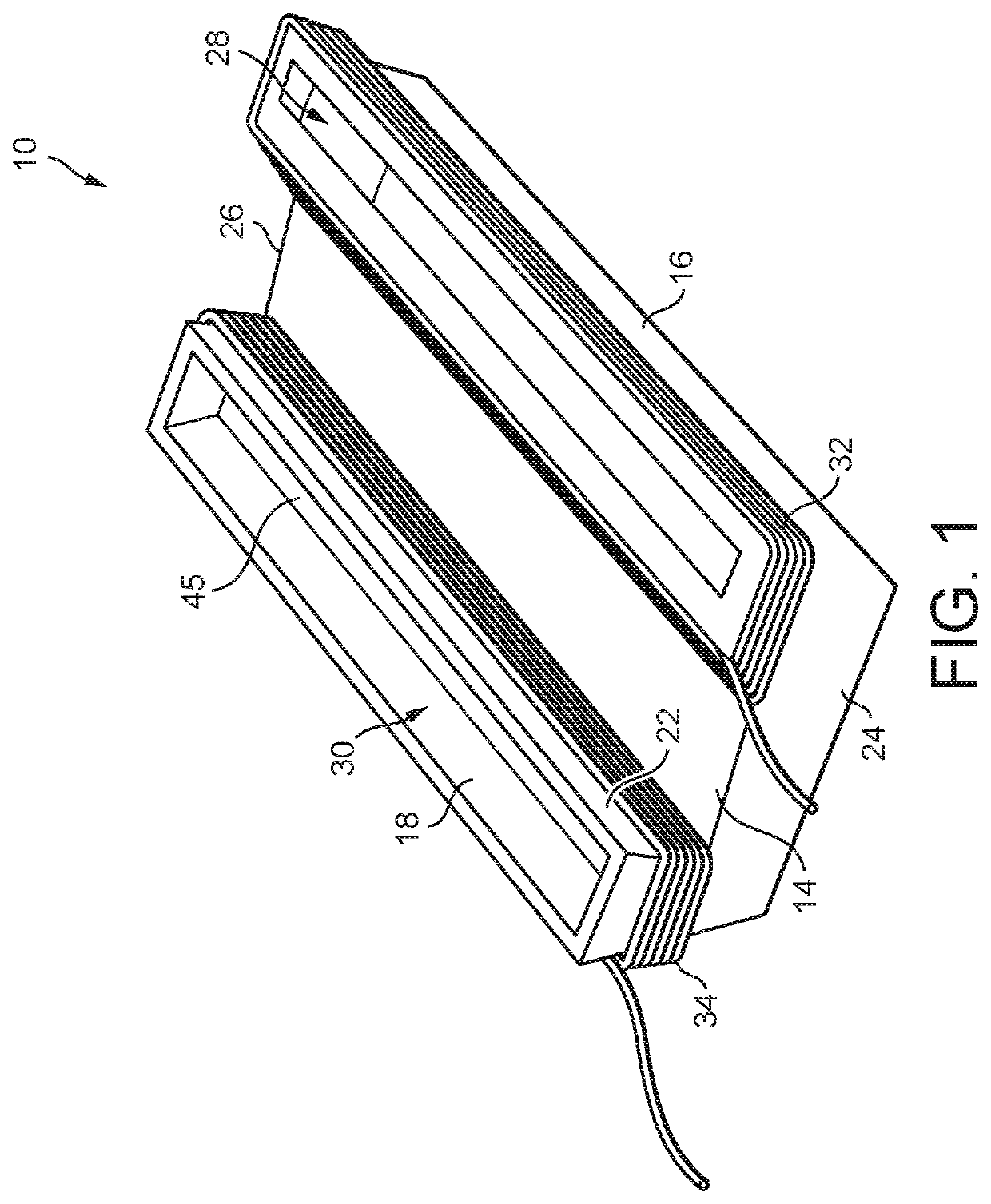
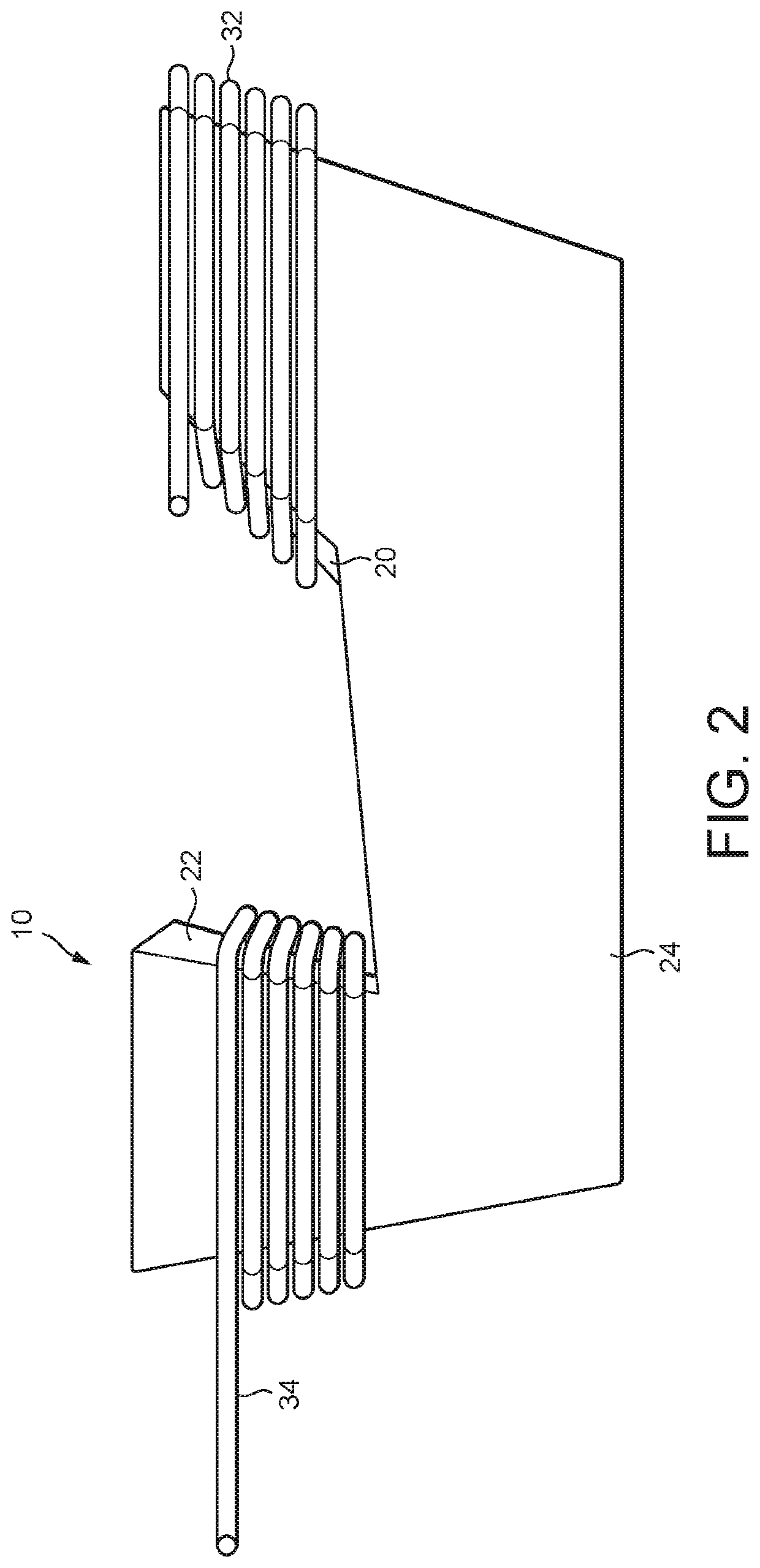
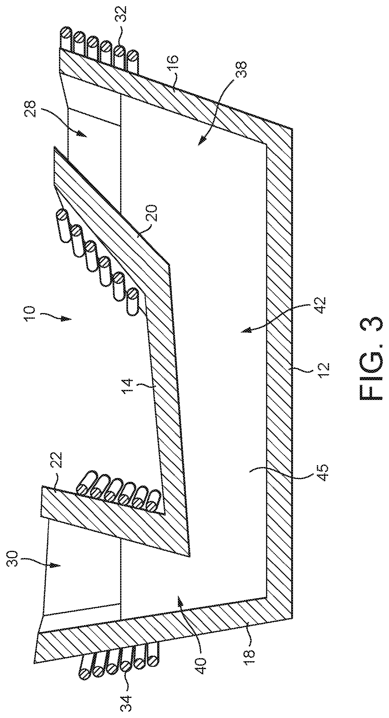
[0024]FIGS. 1 to 3 illustrate a crucible 10 for use in an evaporator device for applying material to a substrate by vapour deposition. The crucible 10 comprises a base 12, a cover 14, external side walls 16, 18 extending upwardly from the base 12, internal side walls 20, 22 extending upwardly from the cover 14, and side walls 24, 26 connected to the ends of the internal side walls 20, 22. The side walls 16, 20, 24, 26 define an elongate inlet 28 of the crucible 10, and the side walls 18, 22, 24, 26 define an elongate outlet 30 of the crucible 10. In some embodiments, the base 12 and the cover 14 are substantially planar, and the cover 14 is arranged at an angle to, and so non-parallel with, the base 12.

[0025]A first heater 32 is located beneath the inlet 28, and is in the form of a coil extending about upper portions of the side walls 16, 20, 24, 26 of the crucible 10. The first heater 32 may be a resistant heater or an induction heater. A second heater 34 is spaced from the first h...


PUM

PropertyMeasurementUnit
temperatureaaaaaaaaaa
melting pointaaaaaaaaaa

Abstract

An evaporator device incudes a crucible comprising an inlet through which solid material is introduced to the crucible, and an outlet through which vaporised material is released from the crucible. Vapours outgassed from molten material within the crucible are guided away from the outlet.

Description

REFERENCE TO RELATED APPLICATION[0001]This application is a national stage application under 35 U.S.C. 371 of International Application No. PCT / GB2019 / 051521, filed May 31, 2019, which claims the priority of United Kingdom Application No. 1809089.4, filed Jun. 4, 2018, the entire contents of each of which are incorporated herein by reference.FIELD OF THE DISCLOSURE[0002]The present disclosure relates to a vapour deposition evaporator for depositing material to a substrate. More specifically, the present disclosure relates to a steady state vapour deposition evaporator device for continuous deposition of material onto a substrate. Even more specifically, the present disclosure relates to a steady state vapour deposition evaporator device for continuous deposition of metallic material onto a moving substrate.BACKGROUND OF THE DISCLOSURE[0003]Thin films of metallic material can be deposited onto a substrate using vapour deposition techniques. Conventional methods include melting materi...

Claims


Application Information

Patent Timeline
Patent Type & Authority Applications(United States)
IPC IPC(8): C23C14/24C23C14/26
CPCC23C14/243C23C14/26C23C14/246C23C14/54C23C14/56
Inventor RENDALL, MICHAEL EDWARD
Owner DYSON TECH LTD
Why Eureka
Try Eureka