Method for uniformly and fast depositing thin film on surface of continuous fiber/strip

A continuous fiber and fiber filament technology is applied in the field of high-speed and uniform deposition of metal/compound films to achieve the effects of high-speed and high-uniform deposition of films, increased density, and low damage

Inactive Publication Date: 2013-07-10
INST OF METAL RESEARCH - CHINESE ACAD OF SCI
View PDF3 Cites 0 Cited by
  • Summary
  • Abstract
  • Description
  • Claims
  • Application Information

AI Technical Summary

Problems solved by technology

[0006] The object of the present invention is to provide a kind of device and the method for depositing metal / compound thin film uniformly at high speed on the surface of continuous fiber filament / strip, utilize the closed magnetic field system that four unbalanced magnetron sputtering targets form to solve the problem in fiber filament / strip For the problem of high-speed and uniform film deposition on the surface of the strip, a metal / multi-component film with uniform thickness can be deposited on the surface of the continuous fiber filament / strip at high speed to achieve the continuity and stability of the deposition process

Method used


Image

  • Method for uniformly and fast depositing thin film on surface of continuous fiber/strip
  • Method for uniformly and fast depositing thin film on surface of continuous fiber/strip
  • Method for uniformly and fast depositing thin film on surface of continuous fiber/strip

Examples


Embodiment 1

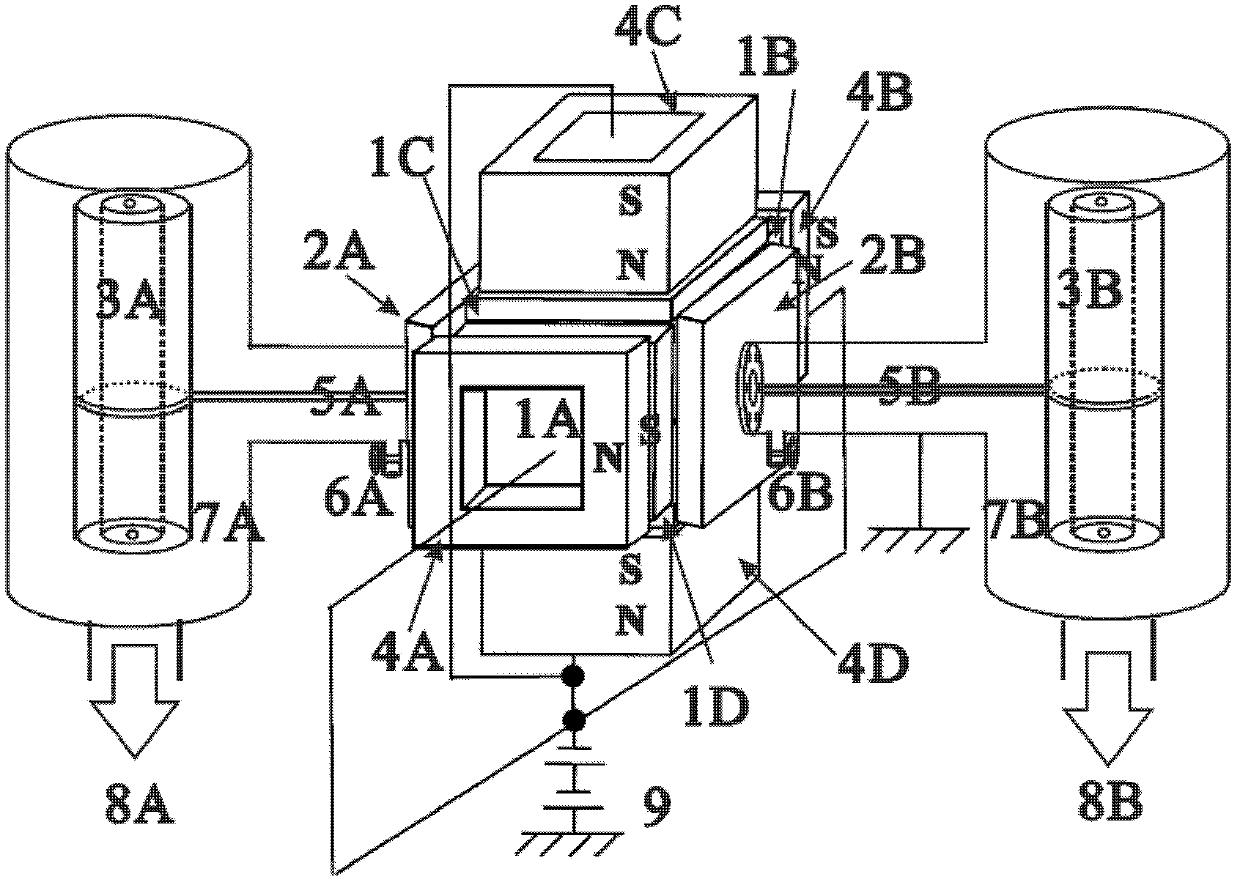
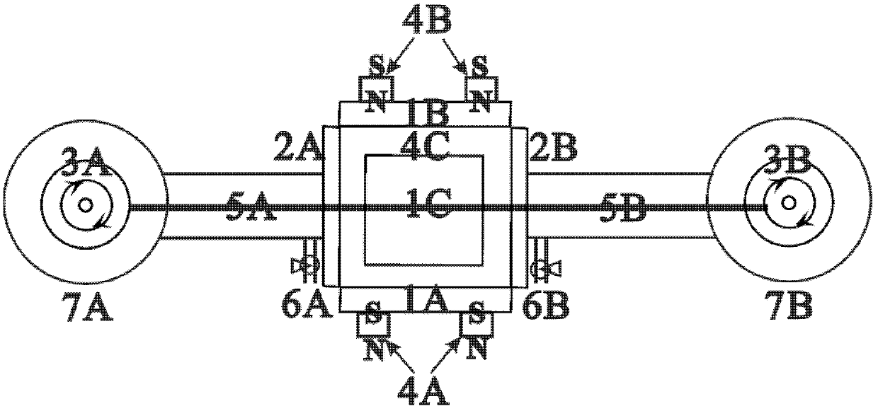
[0044] Such as Figure 1-2 As shown, the entire vacuum system of the device of the present invention mainly includes: the first group of targets (the first group of target A side 1A and the first group of target B side 1B), the second group of targets (the second group of target C side 1C and the second group of targets D surface 1D), shielding plates at both ends (shielding plate 2A and shielding plate 2B), tension-controllable winding workpiece turret (injection turret 3A and sample output turret 3B), magnet System (magnet system A part 4A, magnet system B part 4B, magnet system C part 4C and magnet system D part 4D), filaments / strips (fibers / strips at the inlet end 5A and filaments / strips at the outlet end belt 5B), sputter gas inlets (sputter gas inlet 6A and sputter gas inlet 6B), vacuum chambers (vacuum chamber 7A and vacuum chamber 7B), vacuum pumps (vacuum pump 8A and vacuum pump 8B ), magnetron sputtering DC / IF pulse power supply 9, etc., the specific structure is as...

Embodiment 2

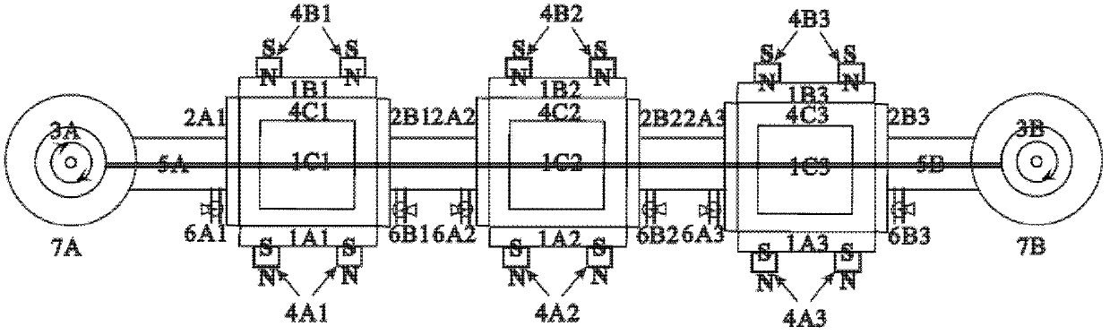
[0050] Such as image 3As shown, the device of the present invention can adopt a whole vacuum system composed of three (more) sealed cuboids / cubes and winding turret vacuum chambers, and the three sealed cuboids / cubes are connected to the winding turret in pairs, and the The turret 3A is connected to the left part of the first sealed cuboid / cube, the right part of the first sealed cuboid / cube is connected to the left part of the second sealed cuboid / cube, and the The right part is connected with the left part of the third sealed cuboid / cube, and the right part of the third sealed cuboid / cube is connected with the sampling turret 3B; the fiber filament / strip 5A at the injection end is wound on the sample turret 3A, the filament / strip 5B at the sample outlet is wound on the sample outlet turret 3B; the vacuum chambers 7A and 7B are connected to the sealed cuboid / cube, and the winding workpiece turret is located in it. In the first sealed cuboid / cube, the A surface 1A1 of the fi...


PUM

PropertyMeasurementUnit
thicknessaaaaaaaaaa
thicknessaaaaaaaaaa

Abstract

The invention belongs to the field of thin film preparation, in particular to a device and a method for uniformly and fast depositing a metal / compound thin film on the surface of a continuous fiber / strip, and solves problems in uniformly and fast depositing a thin film on the surface of the continuous fiber / strip. The device comprises a vacuum closed cuboid or cube and two tension-controllable vacuum cavities connected with the vacuum closed cuboid or cube, wherein two groups of four-side rectangular or square non-equilibrium magnetic controlled targets and two perforated shading plates form the vacuum closed cuboid or cube; the perforated shading plates are the same as each other; workpiece rotating stands are wound in the vacuum cavities; each non-equilibrium magnetic controlled target is driven by a mid-frequency pulse or a direct-current power supply, and generates high-density plasmas in the closed cuboid or cube; the continuous fiber / strip penetrates the high-density plasmas directly in such a manner that the plasmas uniformly encircle the fiber / strip; and a nano thin film is uniformly deposited the surface of the whole continuous fiber / strip. According to the invention, a film can be coated on the fiber / strip uniformly and fast, so as to enlarge the application range of magnetron sputtering coating.

Description

technical field [0001] The invention belongs to the field of film preparation, in particular to a device and method for uniformly depositing a metal / compound film on the surface of a continuous fiber filament / strip at a high speed. Background technique [0002] For the surface modification of filaments / tapes, it has become a bottleneck problem in this industry. Usually chemical vapor deposition and physical vapor deposition are used to deposit a certain thickness of metal layer / compound layer and their composite coating on the surface of fiber filament / strip. Chemical vapor deposition has strict equipment requirements due to the high deposition temperature and the use of toxic precursor gases; physical vapor deposition can prepare metal or compound films at lower temperatures, including vacuum thermal evaporation, arc ion plating and magnetron sputtering Wait. Arc ion plating has limited its application due to the problem of large particles, while magnetron sputtering can ...

Claims


Application Information

Patent Timeline
Patent Type & Authority Patents(China)
IPC IPC(8): C23C14/35C23C14/56
Inventor 雷浩肖金泉宫骏孙超
Owner INST OF METAL RESEARCH - CHINESE ACAD OF SCI
Why Eureka
Try Eureka