Rolled paper feeding device

Inactive Publication Date: 2005-01-27
NIDEC SANKYO CORP
View PDF9 Cites 3 Cited by
  • Summary
  • Abstract
  • Description
  • Claims
  • Application Information

AI Technical Summary

Benefits of technology

[0016] Further, it is another object and advantage of the present invention to provide a rolled paper feeding device which has a good operability of feeding the paper while restricting the number of switches.
[0017] Further, it is another object and advantage of the present invention to provide a rolled paper feeding device which is capable of easily drawing out the paper manually from the rolled paper.
[0018] Further, it is another object and advantage of the present invention to provide a rolled paper feeding device which is capable of preventing an erroneous operation or the like due to static electricity.
[0019] In order to achieve the above object and advantage, according to an embodiment of the present invention, there is provided a rolled paper feeding device including a holder body which rotatably supports a rolled paper, a cover part one end of which is rotatably supported in a contacting and separating direction with respect to the rolled paper and the other end of which abuts with the rolled paper, a feed roller which is provided in the cover part for feeding a paper of the rolled paper and a drive part which is provided in the cover part for

Problems solved by technology

However, since the weight of the roll of toilet paper is light, the contact pressure is inadequate and thus it is difficult to obtain a strong feeding force.
Especially, when the roll of toilet paper is reduced and its weight becomes light, the drive roller can easily become idle.
In addition, when electric power is not supplied due to battery shortage or power failure, it is difficult to draw out the toilet paper because the pair of rollers has to be rotated manually.
Further, the rolled paper very easily torn.
However, in this case, the number of parts increases and the mechanism becomes more complicated.
Moreover, the entire mechanism becomes larger and thus feels unnatural when the large mechanism is installed in a restroom and thus the design is not preferable.
Further, the setting method for the roll of toilet paper will be different from that of the currently used manual rolled paper holder and thus requires more effort.
However, in the rolled paper feeding device described above, the setting time of the timer has to be adjusted when a user tries to change the feeding length and thus fine adjustment is difficult.
Therefore, operability is not satisfactory.
However, in this case, the number of switches and the cost of the device increases.
Also, the size of each

Method used


Image

  • Rolled paper feeding device
  • Rolled paper feeding device
  • Rolled paper feeding device

Examples


Embodiment Construction

[0049] A rolled paper feeding device in accordance with an embodiment of the present invention will be described in detail below with reference to the accompanying drawings.

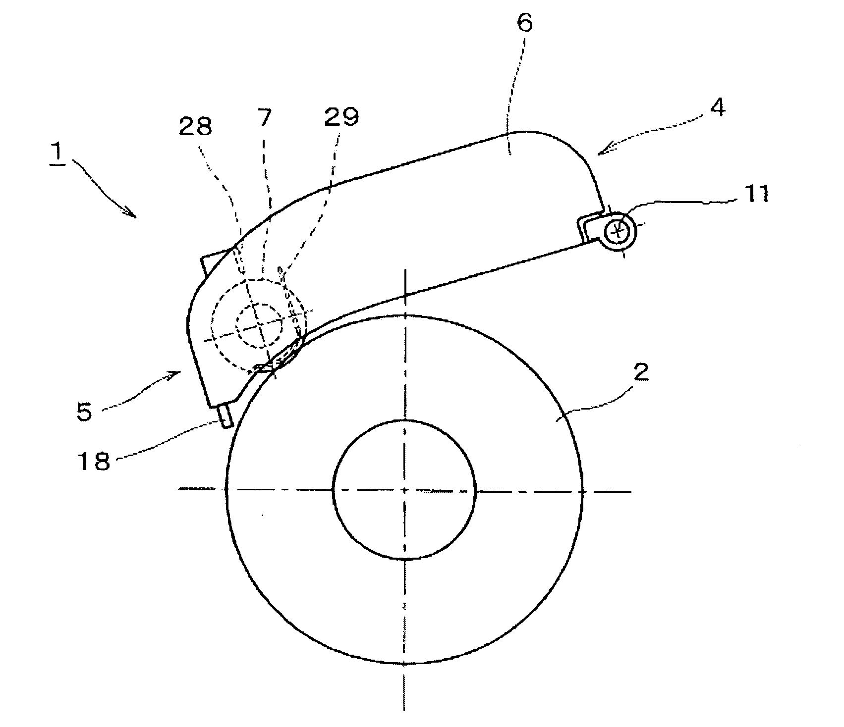
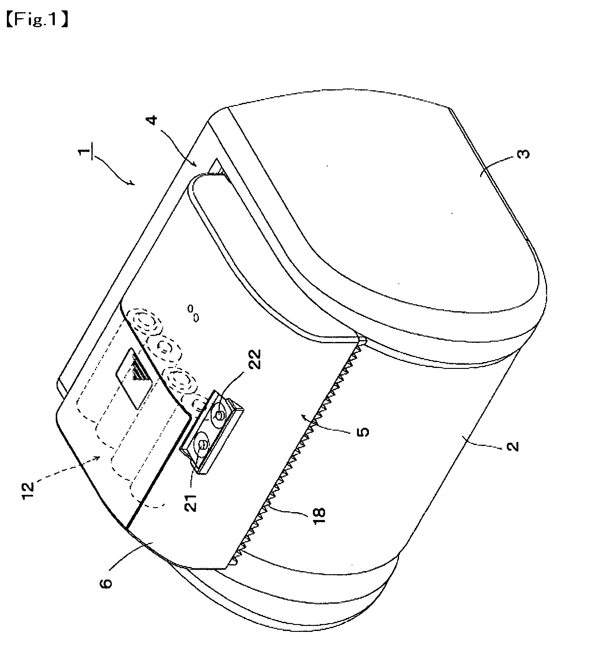
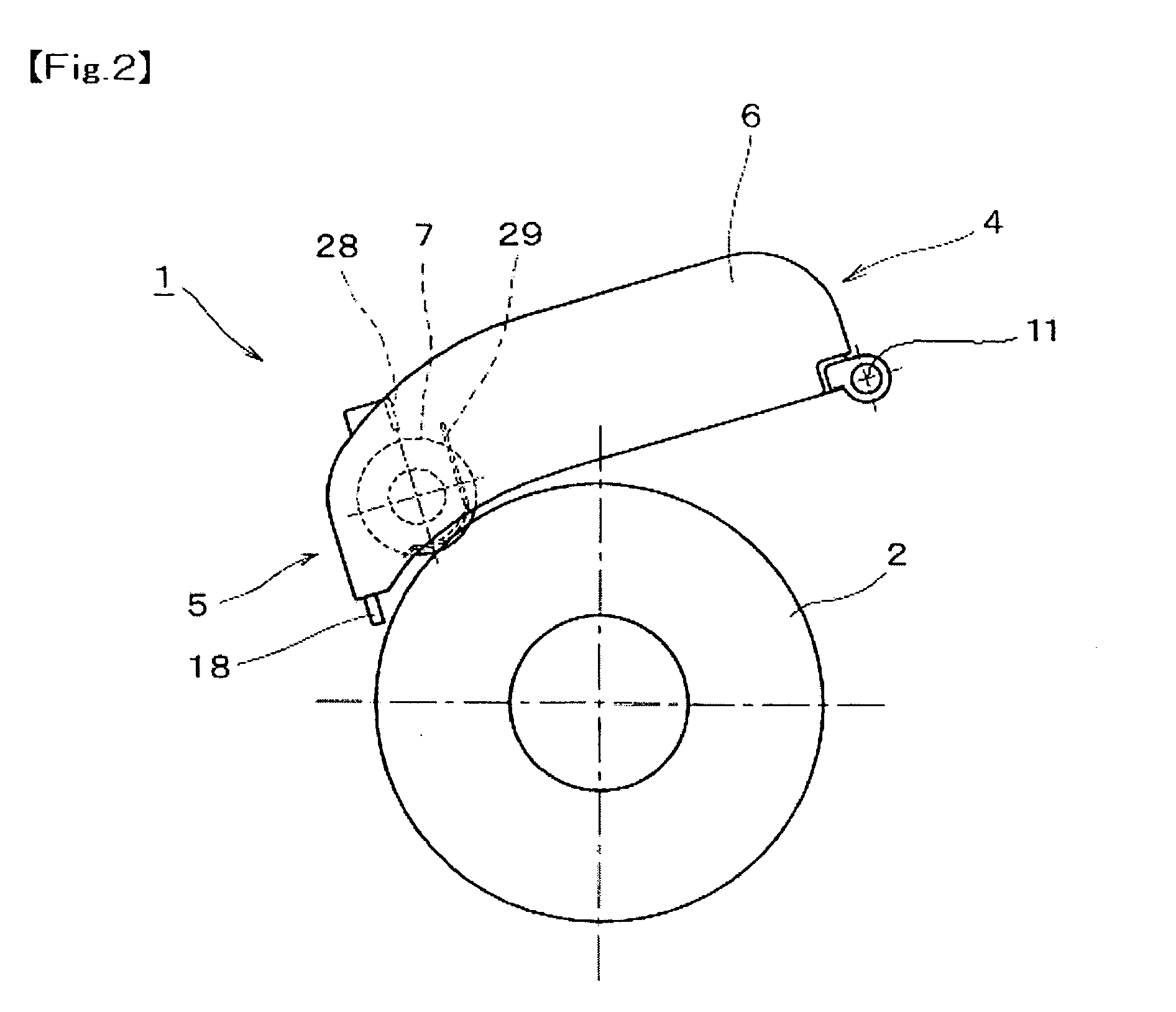
[0050] The rolled paper feeding device 1 includes, as shown in FIG. 1, a holder body 3 for rotatably supporting a rolled paper 2 and a cover part 6 whose one end part 4 is rotatably supported in a direction contacted with or separated from the rolled paper 2. The other end part 5 of the cover part 6 comes into contact with the rolled paper 2. Feed rollers 7 for feeding the paper of the rolled paper 2 and a drive part 8 for driving the feed rollers 7 to rotate are housed in the cover part 6. The feed rollers 7 are disposed on the other end part 5 side farther than the rotational center of the rolled paper 2. In addition, as shown in FIGS. 3 and 4, the drive part 8 includes a drive motor 13, a speed reducing mechanism 14 for transmitting the rotation of the motor 13 to the feed rollers 7 and an one way clutch 17 f...


PUM

PropertyMeasurementUnit
Lengthaaaaaaaaaa
Torqueaaaaaaaaaa

Abstract

A rolled paper feeding device includes a holder body which rotatably supports a rolled paper, a cover part where one end of which is rotatably supported in a contacting and separating direction with respect to the rolled paper and the other end of which abuts with the rolled paper, a feed roller which is provided in the cover part for feeding a paper of the rolled paper, and a drive part which is provided in the cover part for rotationally driving the feed roller. The feed roller is arranged on the other end side with respect to the center of the rolled paper. A control part for controlling the drive part may include a first and a second switches, which can provide three different lengths of the paper to be fed out of the rolled paper.

Description

CROSS-REFERENCE TO RELATED APPLICATIONS [0001] This application claims priority to Japanese Application No. 2003-160334 filed Jun. 5, 2003, Japanese Application No. 2003-164331 filed Jun. 9, 2003, Japanese Application No. 2003-171807 filed Jun. 17, 2003, and Japanese Application No. 2003-175357 filed Jun. 19, 2003, which are incorporated herein by reference. FIELD OF THE INVENTION [0002] The present invention relates to a rolled paper feeding device in which a paper is fed out from a rolled paper by rotating the rolled paper. More specifically, the present invention relates to a rolled paper feeding device which is suitable to feed thin paper such as toilet paper and paper towels. BACKGROUND OF THE INVENTION [0003] One of the conventional rolled paper feeding devices includes a drive roller mounted on a holder that holds a roll of toilet paper. The roll of toilet paper is rotated by the drive roller to feed the paper outside (see Japanese Registered Utility Model No. 3,024,537). [00...

Claims


Application Information

Patent Timeline
IPC IPC(8): B65H16/10
CPCB65H16/106B65H2301/121B65H2301/5133B65H2301/5151B65H2511/11B65H2403/484B65H2220/02
Inventor OWA, JUNJIHOSHI, KAZUKIFUKASAWA, HIROMI
Owner NIDEC SANKYO CORP
Why Eureka
Try Eureka