Reflector antenna with injection molded feed assembly

a technology of reflector antenna and feed assembly, which is applied in the direction of antennas, antenna details, antenna couplings, etc., can solve the problems of only absorbing edge, inter-signal interference, wind load, structural support and manufacturing costs of antennas, and increasing overall weight of shrouds

Inactive Publication Date: 2005-01-27
COMMSCOPE TECH LLC
View PDF9 Cites 40 Cited by
  • Summary
  • Abstract
  • Description
  • Claims
  • Application Information

AI Technical Summary

Problems solved by technology

Cross polarization is a form of interference that occurs when dual signals having different polarizations are simultaneously transmitted and or received by the antenna.
Either of the dual signals may propagate on or reflect from surfaces of the sub reflector and or waveguide partially transforming into the polarization mode of the other signal, creating inter-signal interference.
However, a shroud only blocks and or absorbs edge illumination occurring at angles that intersect with the shroud.
Also, shrouds increa

Method used


Image

  • Reflector antenna with injection molded feed assembly
  • Reflector antenna with injection molded feed assembly
  • Reflector antenna with injection molded feed assembly

Examples


Embodiment Construction

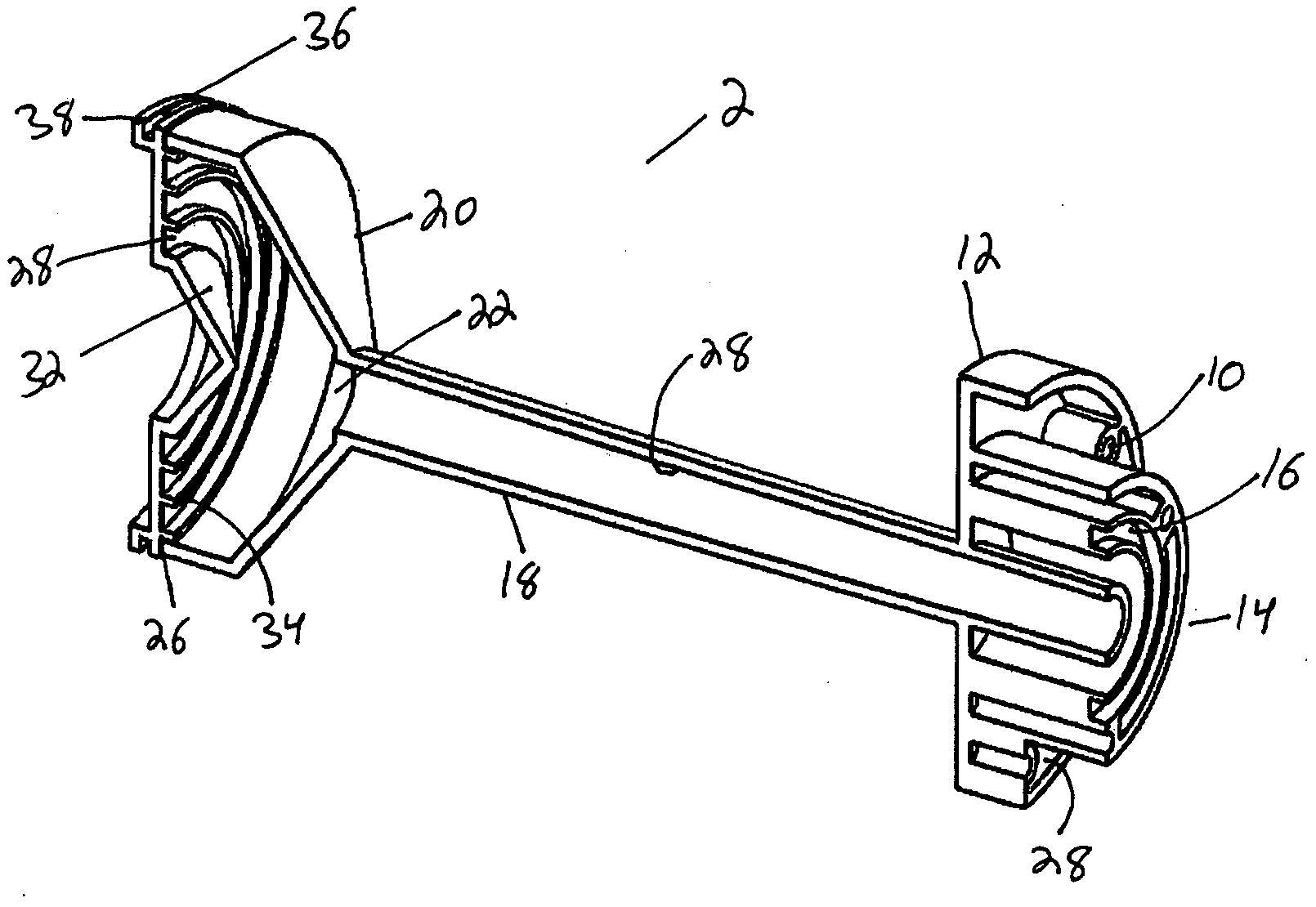
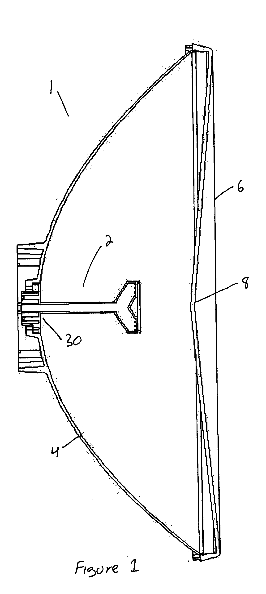
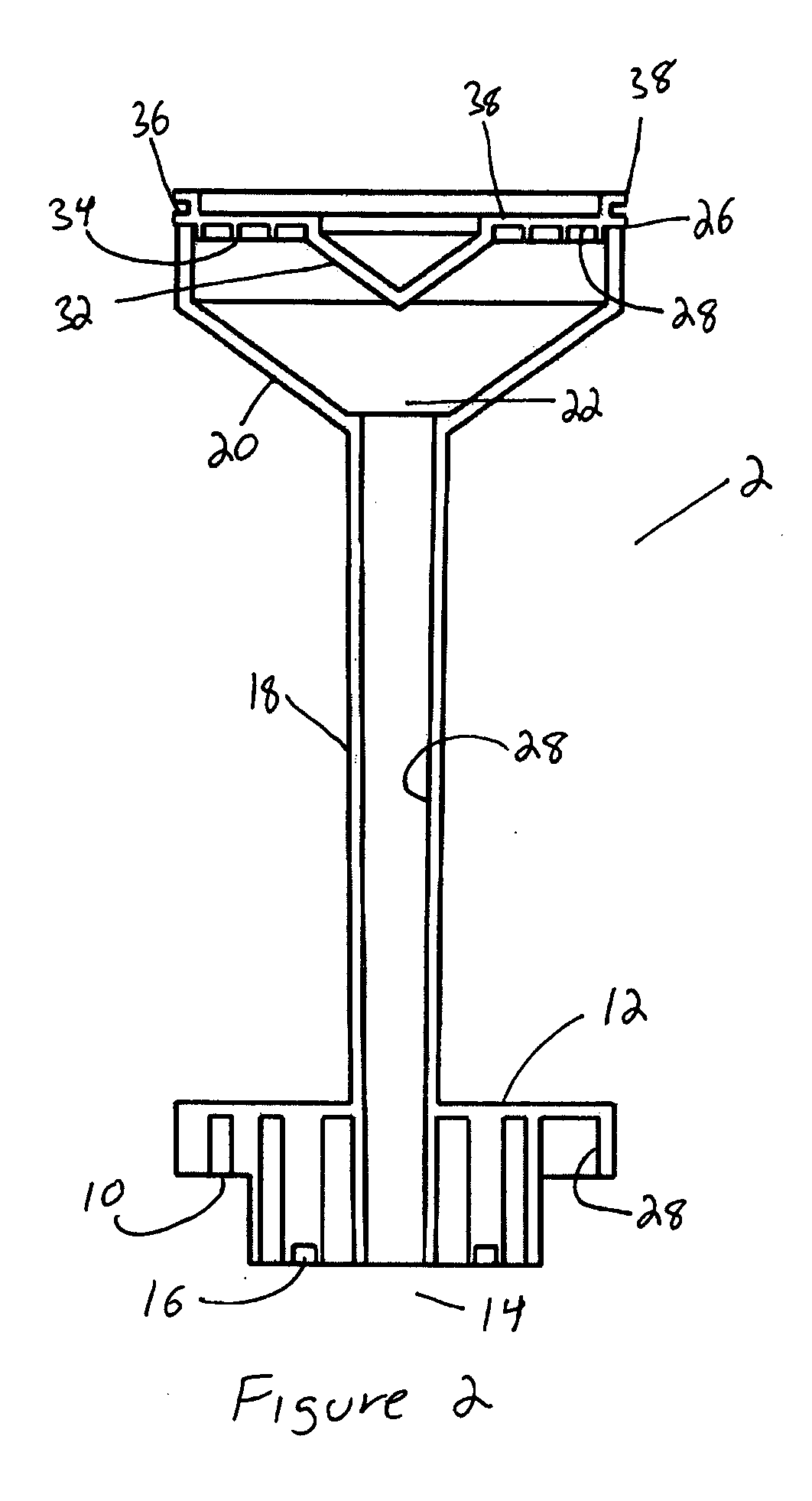
[0020] A first embodiment of a reflector antenna 1 according to the invention is shown in FIG. 1. The feed assembly 2 is mounted at the center of a reflector 4. The reflector 4 is a so-called “deep” reflector with a generally parabolic shape that has been phase corrected. The reflector 4 may be formed from, for example, metal or plastic with an RF reflective coating. A cover 6 formed from dielectric material may also be added to inhibit environmental fouling and or improve wind loading characteristics of the antenna. The cover 6 may be strengthened by a center indentation 8. Also, the inclined dielectric surfaces with respect to the signal direction created by the center indentation 8 of the cover allows energy to pass through with minimum degradation in the return loss performance of the antenna. As shown, the reflector antenna 1 of FIG. 1 is 600 mm in diameter. One skilled in the art will appreciate that the reflector antenna 1 may be configured for smaller or larger diameters as ...


PUM


Abstract

A reflector antenna with a self supported feed assembly that may be formed by injection molding. A waveguide portion of the feed assembly has a dielectric cone at a distal end that supports and retains a sub reflector, for example along a periphery of the sub reflector. A conductive surface coating on an internal surface of the waveguide and a bottom surface of the sub reflector creates surfaces with RF reflective and conductive properties. The return loss of the feed assembly is reduced due to a reduction of the thickness of the material forming the dielectric cone, compared to prior dielectric block designs and a soft boundary condition produced by dielectric coating of the waveguide which aids in reducing reflections to the vertex area of the reflector.

Description

BACKGROUND [0001] 1. Field of the Invention [0002] This invention relates to reflector antennas. More particularly, the invention provides improvements in reflector antenna pattern control, return loss performance and manufacturing cost efficiencies via a self supported sub reflector and feed tube assembly which may be formed by injection molding. [0003] 2. Description of Related Art [0004] Many broadcast and or communications systems require antennas with a highly directional signal reception and or transmission characteristic. Reflector antennas focus a signal received by a dish shaped reflector upon a centrally mounted receiver. Alternatively, a sub reflector mounted at the focus point of the dish directs the signal into a wave guide and there through to the receiver. Because the dish shaped reflector only focuses a signal received from a single direction upon the receiver or sub reflector, reflector antennas are highly directional. When the reflector antenna is used to transmit ...

Claims


Application Information

Patent Timeline
IPC IPC(8): H01Q1/52H01Q13/00H01Q19/13H01Q19/19
CPCH01Q1/528H01Q19/19H01Q19/134
Inventor LEWRY, MATTHEWSYED, JUNAID
Owner COMMSCOPE TECH LLC
Why Eureka
Try Eureka