Magnetic tape recording apparatus

a magnetic tape and recording head technology, applied in the direction of instrumentation, record information storage, filamentary/web carrier operation control, etc., can solve the problems of deterioration in the accuracy of recording track width among the thin film recording heads wb>1/b> to w, track width fluctuations, difficult to reproduce by a thin film multi-reproducing head, etc., to eliminate or reduce the cause of deterioration in the accuracy of recording track width

Inactive Publication Date: 2005-01-27
SONY CORP
View PDF2 Cites 2 Cited by
  • Summary
  • Abstract
  • Description
  • Claims
  • Application Information

AI Technical Summary

Benefits of technology

[0025] As above described, in the magnetic tape recording apparatus of the present invention, one thin film multi-recording head is mounted on the rotary drum, wherein N heads in the thin film multi-recording head are provided to record recording tracks of channel-1 to channel-(N-1) each having a track width narrower than the head width, and in this case, a rotary drum rotation speed and a tape speed are determined by the Equation: V1=Tp·N·(RPS)/sin θ, so as to form recording tracks each having the same track width. Also, in the magnetic tape recording apparatus mounting, M thin film multi-recording head is mounted on the rotary drum, wherein N heads in each of the thin film multi-recording head are provided to record recording tracks of channel-1 to channel-(N-1) each having a track width narrower than the head width, and in this case, a rot

Problems solved by technology

Meanwhile, if a thin film multi-recording head, in which N thin film recording heads W1 to W(N) are disposed at a high density, is mounted on a rotary drum and records on a magnetic tape by helical scanning, there occurs deteriorations in accuracy of recording track width amon

Method used


Image

  • Magnetic tape recording apparatus
  • Magnetic tape recording apparatus
  • Magnetic tape recording apparatus

Examples


Embodiment Construction

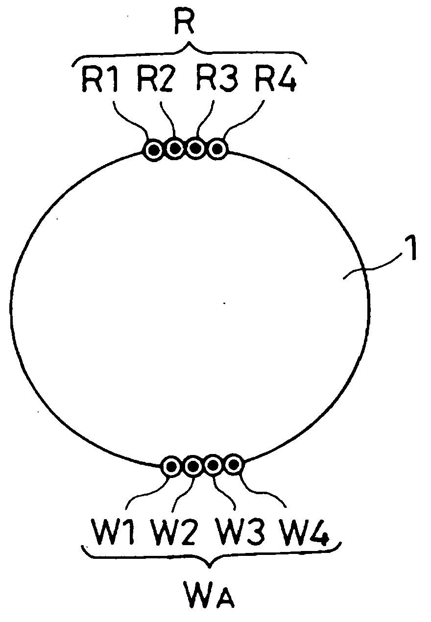
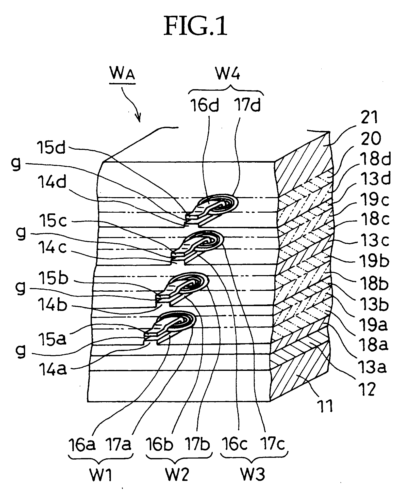
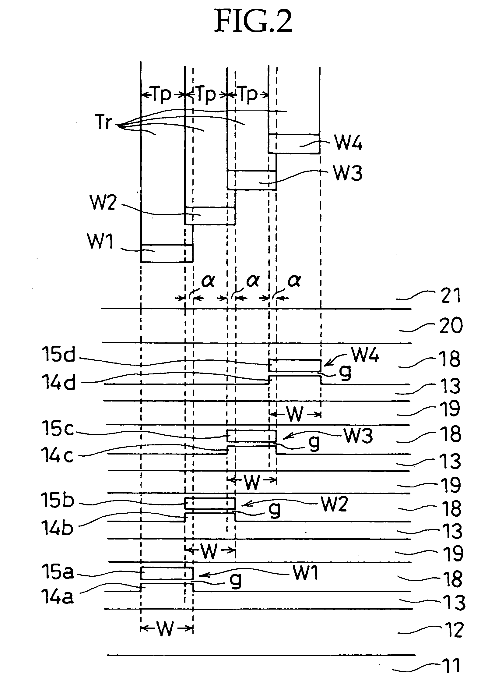
[0044] Details of the present invention will be described below based on respective preferred embodiments shown in the accompanying drawings. FIGS. 1 to 6 show a first preferred embodiment of the present invention, and relate to a magnetic tape recording apparatus in which a thin film multi-recording head WA having N recording heads or head gaps constructed as shown in FIG. 1 is mounted on the peripheral part of a rotary drum 1 as shown in FIG. 3, thereby permitting continuous helical scan recording performing the same azimuth angle and the same track pitch.

[0045] The thin film multi-recording head WA mounted on the rotary drum 1 is made by the technique disclosed in the aforesaid Patent Document 3. As shown in FIG. 1, first to fourth thin film recording heads W1 to W4 (the number N=4) having the same azimuth angle are formed so as to be overlapped α at their respective end portions on the adjacent side when viewed from the direction of lamination, and sandwiched from the direction...


PUM


Abstract

In a helical scan type magnetic tape recording apparatus, one thin film multi-recording head is mounted on a rotary drum, wherein the multi-recording head includes N recording heads for recording N recording tracks at a predetermined track angle on a magnetic tape by one rotation of the rotary drum to perform recording for forming continuous recording tracks having the same track pitches, by determining rotary drum rotation and a tape speed in accordance with equation V1=Tp·N·(RPS)/sin θ, such that (N-1) recording tracks having the same track pitches narrower than the head width and one recording track having a wider track width than that are formed by a first rotation of the drum, then by a second rotation, a preceding recording head overwrites the recording track having the wider track width to form a recording track having a track width equal to the track width of the recording track.

Description

CROSS REFERENCE TO RELATED APPLICATION [0001] This application claims priority from Japanese Priority Document No. 2003-175834, filed on Jun. 20, 2003 with the Japanese Patent Office, which document is hereby incorporated by reference. BACKGROUND OF THE INVENTION [0002] 1. Field of the Invention [0003] The present invention relates to a helical scan type magnetic tape recording apparatus that records a plurality of recording tracks simultaneously with a thin film multihead having a plurality of head gaps, and in which the number of rotations of a rotary drum and a tape speed are determined so as to form recording tracks having the same track pitches. [0004] 2. Description of Related Art [0005] Conventionally, as a helical scan type magnetic tape recording apparatus, there has been proposed in, for example, the following Patent Documents 1 and 2. [0006] Patent Document 1: Japanese Patent Publication No. Heisei-8-34025 [0007] Patent Document 2: Japanese Patent No. 2513204 [0008] In th...

Claims


Application Information

Patent Timeline
IPC IPC(8): G11B5/31G11B5/29G11B5/53G11B15/14G11B15/46G11B15/467G11B15/665G11B21/04
CPCG11B5/534G11B15/6653G11B15/4671G11B15/1875
Inventor OZUE, TADASHI
Owner SONY CORP
Why Eureka
Try Eureka